Section 03
ENGINE
Subsection 10
(CRANKSHAFT/BALANCER SHAFT)
VMR2004_133_03_10A.FM
03-10-5
TIMING CHAIN GUIDE
Removal
Remove:
– engine from vehicle
(refer to REMOVAL AND INSTALLATION)
– magneto and rotor (refer to MAGNETO)
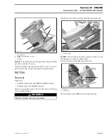
– bearing screw at the bottom of chain guide.
Pull the chain guide downward to remove it.
Inspection
Check chain tensioner guide for wear, cracks or other
damages. Replace if necessary.
Installation
Clean bearing screw threads then apply Loctite 243
on the screw threads.
Install the guide in crankcase housing then torque
bearing screw to 10 N•m (89 lbf•
in
).
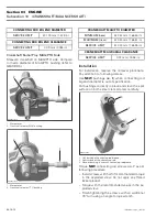
1. Chain tensioner guide
2. Bearing screw
3. Crankcase MAG side
Reinstall all removed parts in accordance with the
proper installation procedures.
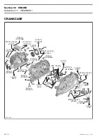
CRANKCASE
To reach the balancer shaft and the crankshaft, it
is necessary to separate the crankcase.
The procedures to remove, inspect and install the
balancer shaft and the crankshaft are explain fur-
ther in this section. For all gearbox parts refer to
GEARBOX).
Removal
Remove:
– engine from vehicle
(refer to REMOVAL AND INSTALLATION)
– magneto housing cover and rotor
(refer to MAGNETO SYSTEM)
NOTE:
Oil pump removal from crankcase MAG
side not necessary, but recommended to see con-
dition of oil pump (refer to LUBRICATION SYS-
TEM).
– output shaft (refer to GEARBOX)
– timing chain (see TIMING CHAIN above)
– cylinder head and cylinder
(refer to CYLINDER AND HEAD)
– drive pulley (refer to CVT, see DRIVE PULLEY).
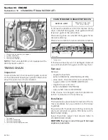
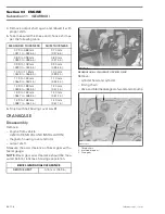
Measure axial clearance between the crankshaft
no. 3
and crankcase PTO
no. 5
with a feeler gauge.
1. Feeler gauge
3
R400motr48A
1
2
CRANKSHAFT AXIAL CLEARANCE
MINIMUM (new)
0.1 mm (.0039 in)
MAXIMUM (new)
0.4 mm (.0157 in)
1
R400motr22A

