Section 03
ENGINE
Subsection 11
(GEARBOX)
03-11-20
VMR2004_134_03_11A.FM
Example
Shim on MAG side:
The measure
A
is 2 mm (.0787 in).
Note the measure indicates on bevel gear in the
box B
. Example: 37.760 mm (1.487 in).
Measure the distance
C
then indicates its value in
the
box C
. Example: 34.040 mm (1.340 in).
B - C - A = D
(37.760 - 34.040 - 2 = 1.72 mm).
In accordance with the appropriate table, you need
a shim number
170
.
Shim on PTO side:
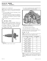
Measure the distance
F
. Indicate this value in the
box F
. Example: 51.800 mm (2.039 in).
Measure the distance
G
. Note this value in the
box G
. Example: 39.080 mm (1.539 in).
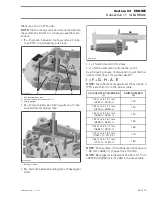
Measure the distance between both butting sur-
face of bevel gear shaft. This is the value
H
. Exam-
ple: 85.680 mm (3.373 in).
F + G - H - A - E = I
(51.800 + 39.080 - 85.680 - 2 - 1.70 = 1.50 mm).
NOTE:
The shim number 170 represents a value
equal at 1.70 mm (
.0669 in). If a shim 160 was re-
quired, its value would be 1.60 mm (.0630 in).
In accordance with the appropriate table, you need
a shim number
140
.
Installation
For installation, reverse the removal procedure.
Pay attention to the following details.
CAUTION:
Don’t forget thrust washer
no. 15
and
no. 22
.
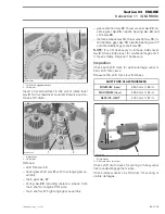
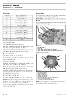
First install intermediate gear then main shaft and
afterward the bevel gear.
1. Intermediate gear
2. Main shaft
3. Thrust washer after main gear on bevel gear
4. Thrust washer between distance sleeve and reverse gear
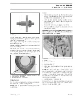
Install the shift drum.
1. Parking stop location
2. Reverse stop location
3. Neutral stop location
4. High gear stop location
5. Low gear stop location
6. Contact to stop location for neutral/park position
7. Contact to reverse stop location
8. Pin to align isolating and index washer
NOTE:
Run all gears as a final function check be-
fore reassembling crankcase MAG.
LETTER
MEASUREMENT 1
A
2 mm (.0787 in)
B
37.760 mm (1.487 in)
C
34.040 mm (1.340 in)
D
1.72 mm (.068 in)
E
170
F
51.800 mm (2.039 in)
G
39.080 mm (1.539 in)
H
85.680 mm (3.373 in)
I
1.500 mm (.059 in)
J
140
2
R400trans30A
4
1
3
3
8
R400motr212A
1
2
7
4
6
5

