background image

OPERATION 

Brake 

Brake reduces the time required to stop the motor. 
During braking an increased noise level from the motor may be audible. This is a normal part of motor braking. 


When brake is selected, the EMX3 uses DC injection to slow the motor.     
EMX3 braking: 


Does not require the use of a DC brake contactor 


Controls all three phases so that the braking currents and associated heating are evenly distributed through the 
motor. 


CAUTION 
If the brake torque is set too high, the motor will stop before the end of the brake time and the motor will suffer 
unnecessary heating which could result in damage.    Careful configuration is required to ensure safe operation of the 
starter and motor. 

A high brake torque setting can result in peak currents up to motor DOL being drawn while the motor is stopping.   
Ensure protection fuses installed in the motor branch circuit are selected appropriately. 


CAUTION 
Brake operation causes the motor to heat faster than the rate calculated by the motor thermal model.    If you are using 
brake, install a motor thermistor or allow sufficient restart delay (parameter 4M).   


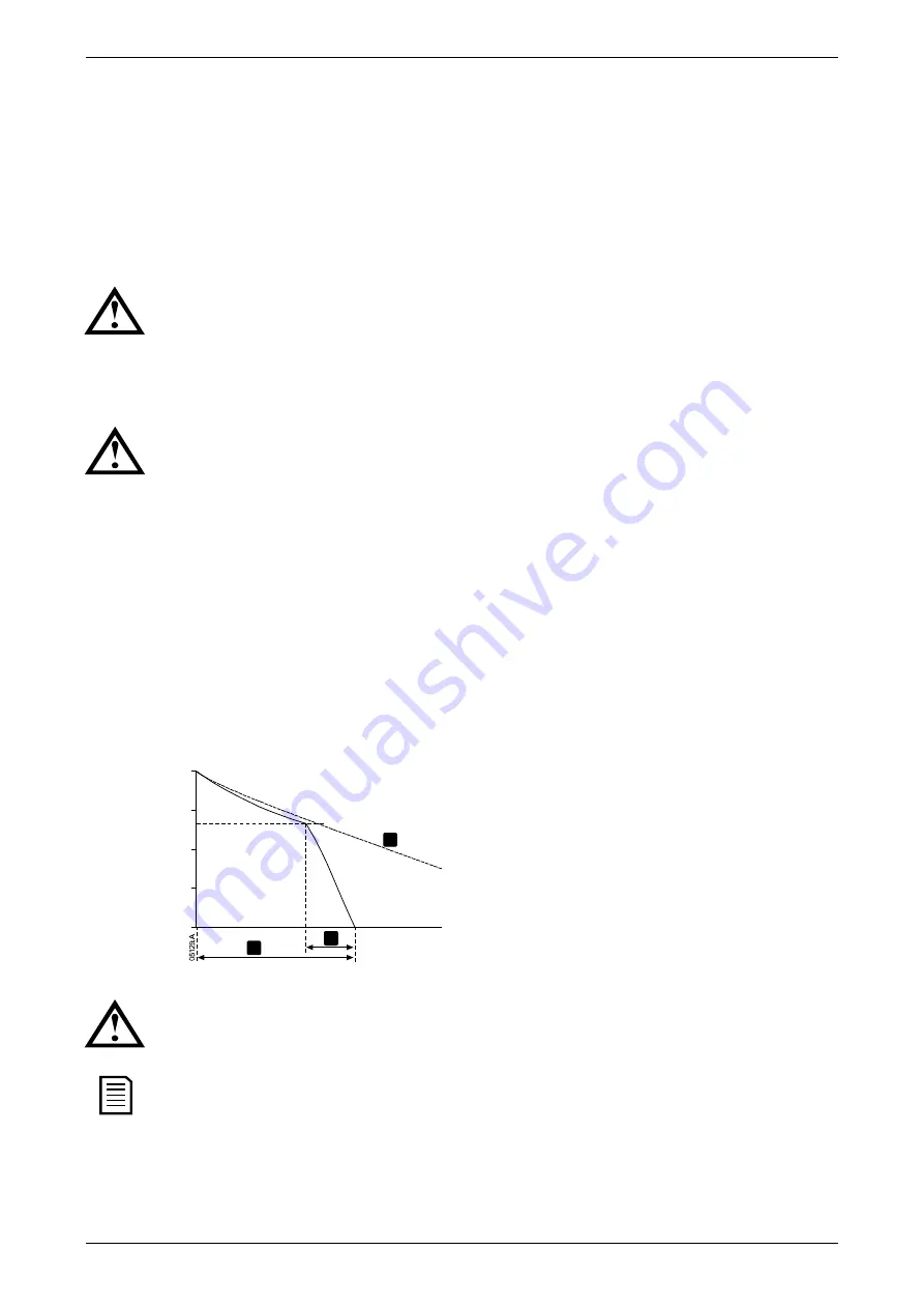
Braking has two stages: 


Pre-brake: provides an intermediate level of braking to slow motor speed to a point where full brake can be operated 
successfully (approximately 70% speed). 


Full brake: brake provides maximum braking torque but is ineffective at speeds greater than approximately 70%. 


To configure the EMX3 for brake operation: 

1.


Set parameter 2I for the desired stopping time duration (1).    This is the total braking time and must be set sufficiently 
longer than the brake time (parameter 2M) to allow the pre-braking stage to reduce motor speed to approximately 70%. If 
the stop time is too short, braking will not be successful and the motor will coast to stop.     

2.


Set Brake Time (parameter 2M) to approximately one quarter of the programmed Stop Time. This sets the time for the Full 
Brake stage (2). 

3.


Adjust the Brake Torque (parameter 2L) so that the desired stopping performance is achieved. If set too low, the motor will 
not stop completely and will coast to stop by the end of the braking period.   


Sp

ee

100%

75%

0%

50%

25%

1

2

3


1: 

Stop Time

 (parameter 2I) 

2: 

Brake Time

 (parameter 2M) 

3: Coast to stop time 


Time 


CAUTION 
When using DC brake, the mains supply must be connected to the soft starter (input terminals L1, L2, L3) in positive 
phase sequence and parameter 4G 

Phase Sequence

 must be set to Positive Only. 


NOTE 
For loads which may vary between braking cycles, install a zero speed sensor to ensure that the soft starter ends DC 
braking when the motor stops.    This avoids unnecessary heating of the motor. 

For more information on using the EMX3 with an external speed sensor (eg for applications with variable load during the 
braking cycle), refer to 

DC Brake with External Zero Speed Sensor

 on page 66.   


36

 | User Manual (710-04840-00M) 

Summary of Contents for EMX3-0023B

Page 1: ...EMX3 Soft Starter USER MANUAL ...

Page 2: ... 26 8 2 Commissioning Menu Tools 26 8 3 Logs Menu 29 9 Operation 31 9 1 Priority ofCommands 31 9 2 Start Stop andReset Commands 31 9 3 Soft StartMethods 32 9 4 StopMethods 34 9 5 Jog Operation 37 9 6 Inside DeltaOperation 37 10 Programming Menu 38 10 1 Programming Menu 38 10 2 AdjustmentLock 38 10 3 Access Code 39 10 4 QuickSetup 39 10 5 Standard Menu 40 10 6 Extended Menu 41 10 7 Load Save Settin...

Page 3: ...pplication of thisequipment 2017 AuCom Electronics Ltd All Rights Reserved As AuCom is continuously improving its products it reserves the right to modify or change the specification of its products at any time without notice The text diagrams images and any other literary or artistic works appearing in this document are protected by copyright Users may copy some of the material for their personal...

Page 4: ...d by an authorised service agent GROUNDING AND BRANCH CIRCUIT PROTECTION It is the responsibility of the user or person installing the EMX3 to provide proper grounding and branch circuit protection according to local electrical safety codes FOR YOUR SAFETY The STOPfunction of the soft starter does not isolate dangerousvoltages from the outputof the starter The soft starter must be disconnected by ...

Page 5: ...uissance et le radiateur doivent être traités comme étant des éléments sous tension si l appareil est relié au secteur y compris lorsque le démarreur s est mis ensécurité ou s il attend une commande PAR SECURITE La fonction STOP du démarreur progressif n isole pas des tensionsdangereuses de la sortie du démarreur Le démarreur progressif doitêtre déconnecté par un dispositif d isolement électrique ...

Page 6: ...ER L ALIMENTATION PRINCIPALE AVANT D ACCÉDER AU DÉMARREUR OU À LA CHARGE Le démarreur progressif comporte des protections intégrées qui peuvent déclencher des mises en sécurité dans l éventualité de défauts et ainsi arrêter le moteur Des fluctuations de tension des coupures d alimentation et des blocages du moteur peuvent produire des mises en sécurité de celui ci Le moteur pourraitredémarrer une ...

Page 7: ...ampedevent logging Operationalcounters number of starts hours run kWh Performance monitoring current voltage power factor kWh User programmable monitoring screen Customisable protection Motor overload Excess Start Time Undercurrent Instantaneous overcurrent Current imbalance Mains frequency Input Trip Motor thermistor Power circuit Phase sequence Models for all connection requirements 23 A 1600 A ...

Page 8: ...he motor s full load current FLC NOTE For advanced applications refer to Extended Menuon page 41 andParameterDescriptionson page 46 7 Close the Menu by pressing repeatedly 8 Optional Use the built in simulation tools to check that the controlwiring is connected correctly refer to Run Simulation on page 27 9 Connect mains supply cables to starter input terminals 1 L1 3 L2 5 L3 refer to Power Inputa...

Page 9: ... of each protection mechanism toconfirm that the softstarter and associated control circuits are responding correctly Refer to ProtectionSimulationon page 27 for details The output signal simulation simulates output signalling to confirm that outputs and associated controlcircuits are operating correctly Refer to Output SignalSimulationon page 28 for details The simulations are only available when...

Page 10: ...w 100 mm 3 94 inches between the soft starter and solid surfaces EMX3 0360C EMX3 1600C Allow 200 mm 7 88 inches between the soft starter and solid surfaces 3 Soft starters may be mounted side by side with no clearance that is if mounted withoutcommunications modules 4 The soft starter may be mounted on its side Derate the soft starter s ratedcurrent by 15 5 2 Control Terminals Control terminations...

Page 11: ... motor starts a coast to stop or until the end of a soft stop If assigned to a trip function the output activates when a trip occurs If assigned to a flag the output activates when the specified flag is active parameters 7M 7O CAUTION Some electronic contactor coils are not suitable for direct switching with PCB mount relays Consult the contactor manufacturer supplier to confirm suitability Three ...

Page 12: ...ttings after the RTD PT100 input has been reset 5 8 Earth Terminals Earth terminals are located at the back of the soft starter EMX3 0023B EMX3 0105B have one terminal on the input side top EMX3 0145B EMX3 1000B andEMX3 0255C EMX3 1600C have two terminals one on the input side top and one on the output side bottom 5 9 Power Input and Output Configurations Internally Bypassed Models EMX3 0023B EMX3...

Page 13: ...on the input busbars The bypass terminals are L1B L2B L3B The busbars on non bypassed models EMX3 0360C EMX3 1600Ccan be adjusted for topor bottominput and output as required Refer to BusbarAdjustment Procedure on page 93 for step by step instructions All units are manufactured bottom in bottom out L1B L2B L3B 1 L1 3 L2 5 L3 2 T1 4 T2 6 T3 1 L1 3 L2 5 L3 L1B L2B L3B 2 T1 4 T2 6 T3 L1B L2B L3B 1 L1...

Page 14: ... ºCor higher EMX3 0023B EMX3 0105B 05966 E Cable size 6 50 mm2 AWG 10 1 0 Torque 4 Nm 2 9ft lb 11290 A 14 mm 0 55 inch Torx T20 x 150 Flat 7 mm x 150 EMX3 0145B EMX3 0170B EMX3 0220B EMX3 0255B 19 Nm 14 0 ft lb 38 Nm 28 0 ft lb 38 Nm 28 0 ft lb 6 mm 19 mm 8 5 mm M8 08351 B 08352 B 6 mm 19 mm 10 5 mm M10 5 mm 28 mm 11 mm M10 13181 B EMX3 0350B EMX3 0425B EMX3 0500B EMX3 1000B EMX3 0255C 38 Nm 28 0 ...

Page 15: ...e control inputs C31 C32 Stop 3 Motor thermistor input C41 C42 Reset 4A RTD PT100 input 2 wire C53 C54 Programmable input A 4B RTD PT100 input 3 wire C63 C64 Programmable input B 4C RTD PT100 input 4 wire 13 14 Relay output A 5 24 VDC output 23 24 Run relay output 6 Relay outputs 31 32 34 Relay output B 7 Analog output 41 42 44 Relay output C Different modelsrequire control voltage to different te...

Page 16: ...an external bypass contactor Internally bypassed models EMX3 0023B EMX3 0043B EMX3 0050B EMX3 0053B EMX3 0076B EMX3 0097B EMX3 0100B EMX3 0105B EMX3 0145B EMX3 0170B EMX3 0200B EMX3 0220B EMX3 0255B EMX3 0350B EMX3 0425B EMX3 0500B EMX3 0580B EMX3 0700B EMX3 0820B EMX3 0920B EMX3 1000B Non bypassed models EMX3 0255C EMX3 0360C EMX3 0380C EMX3 0430C EMX3 0620C EMX3 0650C EMX3 0790C EMX3 0930C EMX3 ...

Page 17: ...rminals and controlled by the soft starter s run output terminals 23 24 Power connections in line installation externally bypassed EMX3 0255C F1 K1 K1 K2 K2 13039 B M 3 6 T3 2 T1 5 L3 3 L2 1 L1 13 14 4 T2 E T3B T3B T3B 24 23 Power connections in line installation externally bypassed EMX3 0360C to EMX3 1600C 6 T3 2 T1 5 L3 3 L2 1 L1 13 14 4 T2 E K1 K1 L1B L2B L3B K2 24 23 K2 M 3 F1 K1 Main contacto...

Page 18: ...1 L1 E K1 F1 K1 Main contactor strongly recommended F1 Semiconductor fuses optional 13 14 Relay output A Main Contactor default WARNING When connecting the EMX3 in inside delta configuration always install a main contactor or shunt tripcircuit breaker NOTE When connecting in inside delta enter the motor full load current FLC for parameter 1A The EMX3 will automatically detectwhether the motor is c...

Page 19: ...als 23 24 04484 C M 3 6 T3 2 T1 5 L3 3 L2 1 L1 13 14 4 T2 E K1 K1 F1 U1 1 U2 4 V1 2 V2 5 W1 3 W2 6 L2B L1B L3B K2 24 23 K2 K1 Main contactor strongly recommended K2 Bypass contactor external F1 Semiconductor fuses optional 13 14 Relay output A Main Contactor default 23 24 Run relay output Inside delta installation non bypassed 6 T3 2 T1 5 L3 3 L2 1 L1 13 14 4 T2 K1 K1 F1 U1 1 U2 4 V1 2 V2 5 W1 3 W...

Page 20: ...e relay willclose and power factor correctionwill be switched in CAUTION Power factor correction capacitors must be connected to the inputside of the soft starter Connecting power factor correction capacitors to the output side will damage the soft starter 6 6 Short Circuit Protection Devices SCPD Fuses may be installed to protectthe soft starter or the installation Type 1 Coordination Type 1 coor...

Page 21: ...0200B 200 J 18 kA AJT200 RK5 300 A070URD30XXX0450 EMX3 0220B 250 J AJT250 RK5 300 EMX3 0255B 350 RK1 J Not available 18 kA EMX3 0350B 400 J For 3 cycles EMX3 0425B 450 J A070URD33XXX0630 30 kA EMX3 0500B 600 J 30 kA Any 600 A Class J A070URD33XXX0700 For 3 cycles EMX3 0580B 800 L Any 800 A Class L Not available EMX3 0700B 42 kA EMX3 0820B A070URD33XXX1000 42 kA EMX3 0920B 1200 L 85 kA Any 1200A Cl...

Page 22: ...X3 0200B EMX3 0220B EMX3 0255B HLD3600 400 SGLA36AT3600 400 UTS400HU UTS600HU 400 EMX3 0350B HLD3600 600 SGLA36AT3600 600 UTS800HU EMX3 0425B UTS600HU 800 EMX3 0500B CHLD3600 600 SKLA3600AT600 600 UTS800xU 800 30 kA EMX3 0580B CHLD3800 800 SKLA3600AT800 800 EMX3 0700B EMX3 0820B NGH312033E 1200 SKLA36AT1200 1200 UTS1200xU 1200 42 kA EMX3 0920B EMX3 1000B UTS800xU 1200 EMX3 0255C SGLA36AT600 400 UT...

Page 23: ...our local distributor I2t values for Type 2 coordination Model SCR I2t A2s EMX3 0023B 1150 EMX3 0043B 8000 EMX3 0050B 10500 EMX3 0053B 15000 EMX3 0076B EMX3 0097B 51200 EMX3 0100B 80000 EMX3 0105B 125000 EMX3 0145B EMX3 0170B 320000 EMX3 0200B EMX3 0220B EMX3 0255B EMX3 0350B 202000 EMX3 0425B 320000 EMX3 0500B EMX3 0580B 781000 EMX3 0700B EMX3 0820B 1200000 EMX3 0920B 2530000 EMX3 1000B EMX3 0255...

Page 24: ... has tripped The starter is in warning state Local The starter is in Localcontrol mode If the starter is in remote control mode the LocalLED will be off If all LEDs are off the starter is not receiving control voltage Removing and Replacing the Keypad The keypad can be removedfromthe soft starter and mountedremotely on a panel using the remote mounting kit NOTE The keypad can be removedor replaced...

Page 25: ...Starter to Display If any of the settings in the keypad are not validfor the starter the keypad loads the default values 7 2 Displays The keypad displays a wide range of performance information about the soft starter The top half of the screen shows real time information on current or motor power as selected in parameter 8D Use the and buttons to select the information shown on the bottom half of ...

Page 26: ...ls of the mostrecent successful start start duration seconds maximum start current drawn as a percentage of motor full load current calculatedrise in motor temperature Last start 010 s 350 FLC Temp 5 Date and Time The date time screen shows the current system date and time 24 hour format For details on setting the date and time refer to SetDate and Time on page 26 Performance Graph The performance...

Page 27: ... date time screen 3 Press the button to enter edit mode 4 Press the and buttons to select which part of the date or time to edit 5 Use the and buttons tochange the value 6 To save changes press the button The EMX3 willconfirm the changes To cancelchanges press the button Simulation Tools Software simulation functions letyou test the soft starter soperation and control circuits without connecting t...

Page 28: ... STORE to Continue 7 Press The Ready LED flashes and the main contactor relay opens Run Simulation Stopped STORE to Continue 8 Press to return to the commissioning menu Protection Simulation The protection simulation simulates activation of each protection mechanism toconfirm that the softstarter and associatedcontrol circuits are responding correctly To use the protection simulation 1 PressALT th...

Page 29: ...e display The current measuring device should indicate the same level of current as shown on the display If the input output expansion card is fitted the simulation can also be used to test the operation of Relays D E F and Analog Output B Temperature Sensors State This screen shows the state of the motor thermistors and RTD PT100s S Short H Hot C Cold O Open Temp Sensors State Thermistor 0 RTD PT...

Page 30: ... the Logs Menu to open a log press the button to scroll through the entries ineach log press the and buttons to view detailsof a log entry press the button to return to the previous level press the button to close the Logs Menu press repeatedly The Logs Menucan only be opened while viewing the monitoring screens Trip Log The Trip Log stores details of the eight mostrecent trips including the date ...

Page 31: ... reset The resettable counters hours run starts and motor kWh can only be reset if the AdjustmentLock parameter 15B is set to Read Write To view the counters 1 PressALT then LOGS to open the Logs 2 Scroll to counters and press 3 Use the and buttons to scroll through the counters Press to view details 4 To reset a counter press then use the and buttons to select Reset DoNot Reset Press STORE toconf...

Page 32: ... network is always enabled in local control mode andcan be enabled or disabled in remote control mode parameter 6R Comms inRemote Control via the serialcommunication network requires an optional communication module The STOP button on the keypad is always enabled Using the Soft Starter to Control a Motor To soft start the motor press the START button on the keypad or activate the Start remote inpu...

Page 33: ...rrent starting is idealfor applications where the start current must be kept below a particular level Current motor full load current 700 600 500 300 100 400 200 10 20 30 40 50 60 70 80 90 100 1 3 2 1 InitialCurrent parameter 2C 2 CurrentLimit parameter 2D 3 Full voltage current Rotor speed full speed Current Ramp Current ramp soft starting raises the current from a specified starting level 1 to a...

Page 34: ...thatmatches the inherent profile of the application can help smooth out acceleration across the full start time Selecting a dramatically different Adaptive Control profile can somewhat neutralise the inherent profile The EMX3 monitors the motor s performance during each start to improve control for future soft starts Adaptive Control To use Adaptive Control to control starting performance 1 Select...

Page 35: ...ckly at the endof a start or stop increase the gain setting by 5 10 If the motor speed fluctuates during starting or stopping decrease the gain setting slightly NOTE Changing the gain setting resets the starter s adaptive control learning The first start after changing the gain will use constant current 9 4 Stop Methods Soft starters offer a variety of methods for the control of motor stopping Sto...

Page 36: ...e a normal soft stop This allows the EMX3 to learn the characteristics of the connected motor This motor data is used by the EMX3 during subsequent Adaptive Control stops NOTE Adaptive Control willcontrol the load according to the programmed profile Stopping current willvary according to the selected deceleration profile andstop time If replacing a motor connected toan EMX3 programmedfor Adaptive ...

Page 37: ...maximum braking torque but is ineffective at speeds greater than approximately 70 To configure the EMX3for brake operation 1 Set parameter 2Ifor the desired stopping time duration 1 This is the total braking time and must be set sufficiently longer than the brake time parameter 2M to allow the pre braking stage toreduce motor speed toapproximately 70 If the stop time is too short brakingwill not b...

Page 38: ...shortcutkey parameters 8B and8C To stop a jog operation performone of the following Remove the jogcommand Press the STOP button on the keypad Jog willrecommence at the end of a restart delay if the jog command is still present All other commands except the above will be ignored during jog operation 9 6 Inside Delta Operation Adaptive Control Jog Brake and PowerThrough functions are notsupported wi...

Page 39: ...to scroll through parameter groups press the or button to open a submenu press the button to view the parameters in a group press the button to return to the previous level press the button to close the Programming Menu press repeatedly To change a parameter value scroll to the appropriate parameter in the Programming Menu and press to enter edit mode to alter the parameter setting use the and but...

Page 40: ...rameter to suit your exact requirements Always set parameter 1A Motor Full Load Current to match the motor s nameplate full load current The suggested value is the starter s minimum full load current On the display the highlightedvalues are suggested values and the values indicated by a are the loaded values Application Parameter Suggested value Pump Centrifugal Motor Full Load Current StartMode A...

Page 41: ...r Time Model dependent Constant Current 10 seconds 450 40 seconds 30 seconds 10 5 Standard Menu The standard menu provides access tocommonly used parameters allowing the user to configure the EMX3 as requiredfor the application For details of individual parameters refer to ParameterDescriptionson page 46 Parameter Group Default Setting 1 Motor Data 1 1A Motor Full Load Current Model dependent 2 St...

Page 42: ...erature Flag 80 8 Display 8A Language English 8B F1 ButtonAction Auto Start Stop Menu 8C F2 ButtonAction None 8D Display A orkW Current 8E User Screen Top Left Starter State 8F User Screen Top Right Blank 8G User Screen Bottom Left Hours Run 8H User Screen Bottom Right Analog Input 10 6 Extended Menu The Extended Menu provides access to all the EMX3 s programmable parameters Parameter Group Defaul...

Page 43: ... 0m 03s 4J Frequency Check Start Run 4K Frequency Variation 5Hz 4L FrequencyDelay 0m 01s 4M RestartDelay 10s 4N Motor TemperatureCheck Do Not Check 4O Ground FaultLevel 100 mA 4P Ground FaultDelay 0m 03s 4Q Reserved 4R Reserved 4S Reserved 4T Reserved 5 Auto Reset Trips 5A Auto ResetAction Do Not Auto Reset 5B Maximum Resets 1 5C ResetDelay GroupsA B 00m 05s 5D ResetDelay Group C 05 m 6 Inputs 6A ...

Page 44: ...100 7O Motor Temperature Flag 80 7P Analog OutputA Current FLC 7Q Analog A Scale 4 20 mA 7R Analog A Maximum Adjustment 100 7S Analog A Minimum Adjustment 000 7T Analog Output B Current FLC 7U Analog BScale 4 20 mA 7V Analog BMaximum Adjustment 100 7W Analog BMinimum Adjustment 000 8 Display 8A Language English 8B F1 ButtonAction Auto Start Stop Menu 8C F2 ButtonAction None 8D Display A orkW Curre...

Page 45: ...22 F 11B RTD PT100 B C 50 C 122 F 11C RTD PT100C C 50 C 122 F 11D RTD PT100D C 50 C 122 F 11E RTD PT100E C 50 C 122 F 11F RTD PT100 F C 50 C 122 F 11G RTD PT100G C 50 C 122 F 12 Slip Ring Motors 12A Motor Data 1Ramp Single Ramp 12B Motor Data 2Ramp Single Ramp 12C Changeover Time 150 ms 12D Slip Ring Retard 50 15 Advanced Requires Access Code Default 0000 15A AccessCode 0000 15B AdjustmentLock Rea...

Page 46: ...ettings to an internal file In addition to the factory default values file the EMX3 can store twouser defined parameter files These files contain default values until a user file is saved To load or save parameter settings 1 Open the Programming Menu 2 Scroll to Load Save Settings and press the button 3 Scroll to the required function and press the button Load Save Settings Load Defaults Load Back...

Page 47: ... 1D Motor Service Factor Range 100 130 Default 105 Description Sets the motor service factor used by the thermal model If the motor runs at full load current it will reach 100 Set according to the motor datasheet NOTE Parameters 1B 1C and 1D determine the trip current for motor overload protection The default settings of parameters 1B 1C and 1D provide Motor Overload Protection Class 10 Trip Curre...

Page 48: ...ain contactor is installed the contactor mustremain closed until the end of the stop time Use one of the programmable relays tocontrol the main contactor 2J Adaptive Stop Profile Options Early Deceleration Constant Deceleration default Late Deceleration Description Selects which profile the EMX3 will use for an Adaptive Control softstop 2K Adaptive Control Gain Range 1 200 Default 75 Description A...

Page 49: ...oft starter will not auto stop Timer The soft starter will auto stop after a delay from the next start as specified in parameter 3D Clock The soft starter will auto stop at the time programmed in parameter 3D Description Selects whether the soft starter will auto stop after a specified delay or at a time of day 3D Auto Stop Time Range 00 01 24 00 hours minutes Default 1 minute Description Sets the...

Page 50: ...oft starter will allow at a start During its pre start checks the starter examines the sequence of the phases at its input terminals and trips if the actual sequence does not match the selected option 4H Current Imbalance Range 10 50 Default 30 Description Sets the trip pointfor current imbalance protection 4I Current Imbalance Delay Range 0 00 4 00 minutes seconds Default 3 seconds Description Sl...

Page 51: ...iption Sets the trip pointfor ground fault protection 4P Ground Fault Delay Range 0 01 4 00 minutes seconds Default 3 seconds Description Slows the EMX3 s response to ground faultvariation avoiding tripsdue to momentary fluctuations NOTE Ground fault protection is only available if the RTD PT100 and ground fault protectioncard is fitted 4Q Reserved This parameter isreservedfor internal use 4R Rese...

Page 52: ...stop cycle Input Trip N O Input A can be used to trip the soft starter When parameter 6A isset to Input Trip N O aclosed circuit across C53 C54 trips the soft starter Input Trip N C When parameter 6A is set to Input Trip N C an open circuit across C53 C54 trips the soft starter Local Remote Select Input A can be used to select between local and remote control instead of using the LCL RMT button on...

Page 53: ...nd Description Sets a delay before an input tripcan occur The initial delay is counted from the time a start signal is received The state of the input is ignored until the initial delay has elapsed 6F 6G 6H 6I 6J Input B Trip Parameters 6F 6Jconfigure the operation of Input B in the same way as parameters 6A 6E configure InputA Refer to InputA for details 6F InputB Function Default Input Trip N O ...

Page 54: ...reset inputs are still active 6R Comms in Remote Options Disable Control in RMT Enable Control in RMT default Description Selects whether the starter will accept Start and Stop commandsfrom the serial communication network when in Remote mode The Reset and Local Remote Control commands are alwaysenabled 7 Outputs The EMX3 has three programmable outputs whichcan be used to signal different operatin...

Page 55: ...elays B C D E F Parameters 7D 7L configure the operation of Relays B C D E andF in the same way as parameters 7A 7Cconfigure Relay A Refer to Relay A Function for details Relay B is a changeover relay 7D Relay B Function Default Run 7E Relay BOnDelay 7F Relay BOff Delay Relay C is a changeover relay 7G Relay C Function Default Trip 7H Relay C OnDelay 7I Relay C Off Delay RelaysD E and F are only a...

Page 56: ...um motor kVA 3 x motor FLC x mains reference voltage Description Selects which information will be reported via the analog output 7Q Analog A Scale Range 0 20 mA 4 20 mA default Description Selects the range of the analog output 7R Analog A Maximum Range 0 600 Default 100 Description Calibrates the upper limit of the analog output to match the signalmeasured on an external currentmeasuring device ...

Page 57: ...ion option is installed Description Selects which information will be displayed on the programmable monitoring screen 8E User Screen Top Left Default Starter State 8F User Screen Top Right Default Blank 8G User Screen Bottom LeftDefault Hours Run 8H User Screen Bottom Right Default Analog Input 8I Graph Data The EMX3 has a real time performance graph to report the behaviour of critical operating p...

Page 58: ...gure parameters 9B 9E to suit the second motor To use the EMX3 with two different motor data sets for the same motor for dual speed motors or applications where starting conditions may vary use parameter 9A to select a single thermal model and configure the starting and stopping profiles asrequired in parameters 10A 10G The soft starter will ignore parameters 9B 9E and will use settingsfrom the pr...

Page 59: ... so that the motor begins to accelerate immediately after a start is initiated If current ramp starting is notrequired set the initialcurrent equalto the current limit 10D Current Limit 2 Range 100 600 FLC Default 350 Description Sets the current limit for constant current and currentramp soft starting as a percentage of motor full load current 10E Adaptive Start Profile 2 Options Early Accelerati...

Page 60: ...tion card has been installed Range 0 250 C Default 50 C Description Sets the trip points for the RTD PT100 inputs 11A RTD A Trip Temp 11B RTD BTrip Temp 11C RTD C Trip Temp 11D RTD D Trip Temp 11E RTD E Trip Temp 11F RTD F Trip Temp 11G RTD G Trip Temp 12 Slip Ring Motors These parameters allow the soft starter to be configured for use with a slip ring motor 12A 12B Motor Data 1 and Motor Data 2 R...

Page 61: ...ends ignoring stop commands and trips Emergency run is controlled using a programmable input CAUTION Continued use of Emergency Runis notrecommended Emergency Run may compromise the starter life as all protections and trips are disabled Using the starter in Emergency Run mode will void the product warranty 15D Shorted SCR Action Options 3 Phase Control Only default PowerThrough Description Selects...

Page 62: ...ten to the event log The default action for all protections is to trip the soft starter Protections 16NGround Faultand 16P 16U RTD PT100 are only available if the RTD PT100 and ground fault protectioncard has been fitted CAUTION Defeating the protection may compromise the starter and motor and should only be done in the case of emergency 16A 16X Protection Actions Options Trip Starter default Warn...

Page 63: ... C24 C64 C63 B7 B8 B6 A2 A1 A3 5 L3 3 L2 C23 E 1 L1 F1 K1 K1 7 6 5 3 2 1 05970 E 8 9 4 1 Controlvoltage model dependent 2 Remote control inputs 3 Motor thermistor input 4 RTD PT100 input 5 24 VDC output 6 Relay outputs 7 Analog output 8 Three phase supply 9 Motor terminals K1 Main contactor F1 Semiconductor fuses optional S1 Start stop contact S2 Reset contact 13 14 Relay output A 23 24 Run relay ...

Page 64: ...4 C63 B7 B8 B6 A2 A1 A3 5 L3 3 L2 C23 E 1 L1 L3B L1B L2B K1 F1 K1 1 Controlvoltage model dependent 2 Remote control inputs 3 Motor thermistor input 4 RTD PT100 input 5 24 VDC output 6 Relay outputs 7 Analog output 8 Three phase supply 9 Motor terminals K1 Bypass contactor external F1 Semiconductor fuses optional S1 Start contact S2 Stop contact S3 Reset contact 13 14 Relay output A 23 24 Run relay...

Page 65: ...s and trips are disabled Using the starter in Emergency Run mode will void the product warranty 32 31 6 T3 2 T1 13 14 P24 COM 4 T2 24 23 34 B10 B11 41 42 44 B5 B4 C31 C32 C41 C42 C53 C54 C24 C64 C63 B7 B8 B6 A2 A1 A3 5 L3 3 L2 C23 E 1 L1 7 6 5 4 3 2 1 8 9 05971 D 1 Controlvoltage model dependent 2 Remote control inputs 3 Motor thermistor input 4 RTD PT100 input 5 24 VDC output 6 Relay outputs 7 An...

Page 66: ...ls S1 Start stop contact S2 Reset contact S3 Auxiliary tripcontact F1 Semiconductor fuses optional 13 14 Relay output A 23 24 Run relay output 31 32 34 Relay output B 41 42 44 Relay output C Parameter settings Parameter 6A InputA Function Select Input Trip N O Assigns the InputA to Auxiliary Trip N O function Parameter 6B InputA Name Select a name eg Low Pressure Assigns a name to Input A Paramete...

Page 67: ...otor thermal model If you are using brake install a motor thermistor or allow sufficient restart delay parameter 4M F1 L3 L2 L1 N E K10 L1 L2 L3 E T1 T2 T3 A2 A3 A1 C23 C24 C31 C32 C41 C42 C53 C54 K10 K11 K10 K11 T3 T2 T1 M 3 K11 K10 A2 06401 E 1 Controlvoltage A Off Ready C23 C24 Start B Start C31 C32 Stop C Run C41 C42 Reset D Stop C53 C54 Programmable input A Starter Disable E Zero speed 2 Moto...

Page 68: ...Remote control inputs K13 Zero speed sensor relay 3 Motor thermistor input K1 Line contactor Run 4 RTD PT100 input K2 Line contactor Brake 5 Relay outputs K1T Run delay timer 6 Three phase supply K2T Brake delay timer 7 Motor terminals K3T Zero speed sensor delay timer A2 Zero speed sensor S1 Start contact F1 Semiconductor fuses optional S2 Stop contact K10 Run relay S3 Reset contact K11 Start rel...

Page 69: ... K11 K3 K10 K2 K11 K1 K2 K3 K1 K3 K1 K3 K2 K2 S1 K1 K10 8 9 5 6 1 2 3 4 7 1 Controlvoltage 2 Remote control inputs 3 Motor thermistor input 4 RTD PT100 input 5 Relay outputs 6 Three phase supply 7 Motor terminals 8 Remote low speed start input 9 Remote high speed start input F1 Semiconductor fuses optional K10 Remote start relay low speed K11 Remote start relay high speed K1 Line contactor high sp...

Page 70: ...3 B7 B8 B6 A2 A1 A3 5 L3 3 L2 C23 E 1 L1 05973 G 7 6 5 4 3 2 1 9 8 1 Controlvoltage model dependent 2 Remote control inputs 3 Motor thermistor input 4 RTD PT100 input 5 24 VDC output 6 Relay outputs 7 Analog output 8 Three phase supply 9 Slip ring induction motor K1 Changeover contactor F1 Semiconductor fuses optional S1 Start stop contact S2 Reset contact R1 Rotor resistance external UserManual 7...

Page 71: ...ions andrecord the time it takes to reach a constant speed with external rotor resistance R1 in the circuit Stop the motor soon after a constant speed has been reached Change parameter 7E to the recorded time value 3 Start the motor under normal load conditions and monitor the motor speed behaviour and motor current when the changeover contactor K1 switches in to short out the rotor resistance R1 ...

Page 72: ...he real time clock or the backup battery voltage is low If the battery is low and the power is off date time settings will be lost The EMX3will continue to soft start and soft stopcorrectly Reprogram the date and time The battery is not removable In order to replace the battery the main control PCB must be replaced Related parameters 16M Controller This is a name selected for a programmable input ...

Page 73: ...ted parameters 16L High Level This is a name selected for a programmable input Refer to Input A trip High Pressure This is a name selected for a programmable input Refer to Input A trip Input A trip One of the soft starter s inputs is set to a trip function and has activated Check the status of the inputs to identify which input hasactivated then resolve the trigger condition Related parameters 6C...

Page 74: ...e than one second The motor winding has overheated Identify the cause of the overheating and allow the motor to cool before restarting The motor thermistor input has been opened NOTE If a valid motor thermistor is no longer used a 1 2kΩ resistor mustbe fitted across terminals B4 B5 Related parameters 16I Network communication between device and network There is a network communication problem or t...

Page 75: ...stor circuit Check that a PT100 RTD is not connected to B4 B5 The thermistor input has been enabled and The resistance at the input has fallen below 20 Ω the cold resistance of most thermistorswill be over this value or A shortcircuit has occurred Check andresolve this condition Related parameters None Time overcurrent The EMX3 is internally bypassed and has drawn highcurrent during running The 10...

Page 76: ...ermal capacity tocomplete the start successfully Wait for the motor to cool before attempting another start The starter may be disabled via aprogrammable input If parameter 6A or 6F is set to Starter Disable and there isan open circuit on the corresponding input the EMX3 will not start If there is no further need to disable the starter close the circuit on the input NOTE Parameter 6Q Local Remote ...

Page 77: ...t and or the second start was different to the first The first Adaptive Control start isactually Constant Current so that the starter can learnfrom the motor characteristics Subsequent starts use Adaptive Control PowerThrough does not operate when selected The starter will trip on Lx Tx Shorted on the first start attempt after control power is applied PowerThrough will not operate if control power...

Page 78: ...3 1200C EMX3 1410C EMX3 1600C must be externally bypassed In line connection AC53b 3 0 10 350 40 ºC 1000 metres AC53b 3 5 15 345 40 ºC 1000 metres AC53b 4 0 20 340 40 ºC 1000 metres AC53b 4 5 30 330 40 ºC 1000 metres EMX3 0023B 23 A 20 A 17 A 15 A EMX3 0043B 43 A 37 A 31 A 26 A EMX3 0050B 50 A 44 A 37 A 30 A EMX3 0053B 53 A 53 A 46 A 37 A AC53b 3 0 10 590 40 ºC 1000 metres AC53b 3 5 15 585 40 ºC 1...

Page 79: ...ºC 1000 metres AC53b 4 5 30 330 40 ºC 1000 metres EMX3 0023B 34 A 30 A 26 A 22 A EMX3 0043B 64 A 59 A 51 A 44 A EMX3 0050B 75 A 66 A 55 A 45 A EMX3 0053B 80 A 80 A 69 A 55 A AC53b 3 0 10 590 40 ºC 1000 metres AC53b 3 5 15 585 40 ºC 1000 metres AC53b 4 0 20 580 40 ºC 1000 metres AC53b 4 5 30 570 40 ºC 1000 metres EMX3 0076B 114 A 96 A 83 A 70 A EMX3 0097B 145 A 123 A 104 A 87 A EMX3 0100B 150 A 132...

Page 80: ...A 351 A 303 A 259 A EMX3 0380C 380 A 380 A 348 A 292 A EMX3 0430C 430 A 413 A 355 A 301 A EMX3 0620C 620 A 614 A 515 A 419 A EMX3 0650C 650 A 629 A 532 A 437 A EMX3 0790C 790 A 790 A 694 A 567 A EMX3 0930C 930 A 930 A 800 A 644 A EMX3 1200C 1200 A 1200 A 1135 A 983 A EMX3 1410C 1410 A 1355 A 1187 A 1023 A EMX3 1600C 1600 A 1600 A 1433 A 1227 A Inside delta connection AC53a 3 10 50 6 40 ºC 1000 met...

Page 81: ...0 A 159 A 135 A EMX3 0220B 220 A 180 A 156 A EMX3 0255B 255 A 205 A 180 A EMX3 0350B 360 A 302 A 240 A EMX3 0425B 425 A 360 A 302 A EMX3 0500B 515 A 384 A 324 A EMX3 0580B 590 A 426 A 360 A EMX3 0700B 700 A 515 A 431 A EMX3 0820B 820 A 605 A 509 A EMX3 0920B 920 A 673 A 590 A EMX3 1000B 1000 A 783 A 720 A Non bypassed models EMX3 0255C 242 A 220 A 160 A EMX3 0360C 360 A 302 A 242 A EMX3 0380C 380 ...

Page 82: ...02 A EMX3 0220B 330 A 270 A 234 A EMX3 0255B 382 A 307 A 270 A EMX3 0350B 540 A 453 A 360 A EMX3 0425B 637 A 540 A 453 A EMX3 0500B 772 A 576 A 486 A EMX3 0580B 885 A 639 A 540 A EMX3 0700B 1050 A 772 A 646 A EMX3 0820B 1230 A 907 A 763 A EMX3 0920B 1380 A 1009 A 885 A EMX3 1000B 1500 A 1174 A 1080 A Non bypassed models EMX3 0255C 363 A 330 A 240 A EMX3 0360C 540 A 453 A 363 A EMX3 0380C 570 A 511...

Page 83: ...EMX3 0220B 44 A 220 A 44 A 330 A EMX3 0255B 51 A 255 A 51 A 382 A EMX3 0255C 51 A 255 A 51 A 382 A EMX3 0350B 70 A 350 A 70 A 525 A EMX3 0360C 72 A 360 A 72 A 540 A EMX3 0380C 76 A 380 A 76 A 570 A EMX3 0425B 85 A 425 A 85 A 638 A EMX3 0430C 86 A 430 A 86 A 645 A EMX3 0500B 100 A 500 A 100 A 750 A EMX3 0580B 116 A 580 A 116 A 870 A EMX3 0620C 124 A 620 A 124 A 930 A EMX3 0650C 130 A 650 A 130 A 97...

Page 84: ...APPENDIX 13 5 Dimensions and Weights EMX3 0023B EMX3 0105B EMX3 0145B EMX3 1000B A B C D E 14408 A A B C D E 14409 A EMX3 0360C EMX3 1600C A B E F C D 14410 B UserManual 710 04840 00M 83 ...

Page 85: ...3 0820B 17 1 12 6 25 2 23 7 11 7 140 0 EMX3 0920B 64 0 EMX3 1000B 141 1 EMX3 0255C 390 15 4 320 12 6 460 18 2 400 15 8 279 11 0 n a 23 50 7 EMX3 0360C 36 EMX3 0380C 79 4 EMX3 0430C 430 320 689 522 300 696 EMX3 0620C 17 0 12 6 27 2 20 6 11 9 27 5 39 5 EMX3 0650C 87 1 EMX3 0790C EMX3 0930C 51 5 113 5 EMX3 1200C 574 500 856 727 361 862 128 5 283 3 EMX3 1410C 22 6 19 7 33 8 28 7 14 3 34 0 130 286 6 EM...

Page 86: ...ernally bypassed models IEC 60947 4 2 Class B and Lloyds Marine No 1 Specification EMX3 0255C to EMX3 1600C Non bypassed models IEC 60947 4 2 Class A1 and Lloyds Marine No 1 Specification 1 This product has been designed as ClassA equipment Use of thisproduct in domestic environments may cause radio interference in which case the user may be required to employ additional mitigation methods Inputs ...

Page 87: ...pere approx Certification UL C UL UL 508 EMX3 0023B EMX3 0425B EMX3 0255C EMX3 1600C ULListed EMX3 0500B EMX3 1000B UL Recognised EMX3 0023B EMX3 0105B IP20 NEMA1 UL Indoor Type 1 EMX3 0145B EMX3 1600C IP00 UL Indoor Open Type IP20 whenfitted with optionalfinger guardkit CE EN 60947 4 2 CCC GB 14048 6 RCM IEC 60947 4 2 Marine EMX3 0023B EMX3 1000B internally bypassed models only Lloyds Lloyds Mari...

Page 88: ...MX3 0145B EMX3 0425B and EMX3 0255C EMX3 1600C to be UL compliant you must use the recommended pressure terminal connector as detailed in the table below Models FLC A No of wires Recommended lugs part No EMX3 0145B 145 1 OPHD 95 16 EMX3 0170B 170 1 OPHD 120 16 EMX3 0200B 200 1 OPHD 150 16 EMX3 0220B 220 1 OPHD 185 16 EMX3 0255B 255 1 OPHD 240 20 EMX3 0350B 350 1 OPHD 400 16 EMX3 0425B 425 2 OPHD 1...

Page 89: ...following additional inputs 6 x PT100 RTD inputs 1 x groundfault input To use groundfault protection a 1000 1 5 VA current transformer is alsorequired Finger Guard Kit Finger guards may be specifiedfor personnel safety Finger guards fit over the soft starter terminals to prevent accidental contact with live terminals Finger guards provide IP20 protection when correctly installed NOTE Finger guards...

Page 90: ...aptive Stop Profile 2K Adaptive ControlGain 2L Brake Torque 2M Brake Time 3 Auto Start Stop 3A Auto StartType 3B Auto StartTime 3C Auto Stop Type 3D Auto Stop Time 4 Protection Settings 4A ExcessStartTime 4B ExcessStartTime 2 4C Undercurrent 4D UndercurrentDelay 4E InstantaneousOvercurrent 4F InstantaneousOvercurrentDelayI 4G Phase Sequence 4H Current Imbalance 4I Current Imbalance Delay 4J Freque...

Page 91: ... Relay A Function 7B Relay AOnDelay 7C Relay AOff Delay 7D Relay BFunction 7E Relay BOnDelay 7F Relay BOffDelay 7G Relay C Function 7H Relay COnDelay 7I Relay COff Delay 7J RelayD Function 7K Relay E Function 7L Relay F Function 7M Low CurrentFlag 7N High CurrentFlag 7O Motor Temperature Flag 7P Analog OutputA 7Q Analog A Scale 7R Analog A Maximum Adjustment 7S Analog A Minimum Adjustment 7T Analo...

Page 92: ...Current 2 10D CurrentLimit 2 10E Adaptive Start Profile 2 10F KickstartTime 2 10G KickstartLevel 2 10H Stop Mode 2 10I Stop Time 2 10J Adaptive Stop Profile 2 10K Adaptive ControlGain 2 10L Brake Torque 2 10M Brake Time 2 11 RTD Temperatures 11A RTD PT100A C 11B RTD PT100 B C 11C RTD PT100C C 11D RTD PT100D C 11E RTD PT100E C 11F RTD PT100 F C 11G RTD PT100G C 12 Slip Ring Motors 12A Motor Data 1R...

Page 93: ... Motor Thermistor 16J Starter Communication 16K NetworkCommunication 16L HeatsinkOvertemperature 16M Battery Clock 16N Ground Fault 16O RTD PT100A 16P RTD PT100 B 16Q RTD PT100C 16R RTD PT100D 16S RTD PT100E 16T RTD PT100 F 16U RTD PT100G 16V Reserved 16W Reserved 16X Low ControlVolts 20 Restricted 92 User Manual 710 04840 00M ...

Page 94: ...th the number of the corresponding terminal on the backplane PCB then unplug the looms 8 Unplug the thermistor fan and current transformer wires from the model board 9 Remove the plastic tray from the starter four screws NOTE Remove the main plastic slowly to avoid damaging the keypad wiring loom which runs between the main plastic and the backplane PCB 08605 A 10 Unscrew and remove the magnetic b...

Page 95: ...tarter Remove the cable ties and unscrew the CTsfrom the bracket 2 Move the CT bracket to the top of the starter Position the CTs for the correct phases then screw the CTs to the bracket For models EMX3 0360C EMX3 0930C the CTs must be placed on an angle the left hand legs of each CT will be on the top row of holesand the right hand legs will be on the bottom tabs 94 User Manual 710 04840 00M ...

Page 96: ...02 China T 86 21 5877 5178 F 86 21 5877 6378 Germany Borsigstraße 6 48324 Sendenhorst Germany T 49 2526 93880 0 F 49 2526 93880 100 Middle East 10th Floor Jumeirah Lakes Towers Dubai UAE T 971 4279 8349 F 971 4279 8399 North America 2528 Lovi Road Building 2 2A Freedom PA 15042 USA T 855 928 2666 855 AUCOM NA 1 724 987 4952 F 1 724 510 3005 http my aucom com ...

Reviews: