


3.2
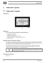
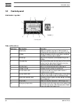
Control panel
Elektronikon regulator
Control panel
Parts and functions
Reference
Designation
Function
1
Start button
Button to start the compressor. LED (8) lights up
indicating that the Elektronikon regulator is operative.
2
Display
Shows messages about the compressor operating
condition, a service need or a fault.
3
Scroll keys
Keys to scroll upwards or downwards through the
display.
4
Tabulator key
Key to select the parameter indicated by the horizontal
arrow. Only the parameters followed by an arrow
pointing to the right can be modified.
5
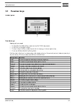
Function keys
Keys to control and program the compressor.
6
Voltage on LED
Indicates that the voltage is switched on.
7
General alarm LED
Is lit if a shut-down warning condition exists or
maintenance is required.
7
General alarm LED
Flashes if a shut-down condition exists, if an important
sensor is out of order or after an emergency stop.
8
Automatic operation LED
Indicates that the regulator is automatically controlling
the compressor.
9
Stop button
Button to stop the compressor. LED (8) goes out.
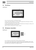
S2
Emergency stop button
Push button to stop the compressor immediately in the
event of an emergency. After remedying the trouble,
unlock the button by pulling it out.
Instruction book
24
2920 1475 06
Summary of Contents for GA110
Page 1: ...GA 90 GA 110 GA 132 GA 160 GA 200 GA 250 GA 315 ...
Page 2: ......
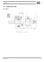
Page 17: ...Flow diagram of GA200 GA250 and GA315 60 Hz Instruction book 2920 1475 06 15 ...
Page 30: ...Menu flow for GA 90 up to GA 315 simplified example Instruction book 28 2920 1475 06 ...
Page 57: ...Dimension drawing of GA90 110 water cooled Instruction book 2920 1475 06 55 ...
Page 60: ...Dimension drawing of GA200 250 and GA315 60 Hz air cooled Instruction book 58 2920 1475 06 ...
Page 64: ...Compressor room example of GA 90 up to GA 160 water cooled Instruction book 62 2920 1475 06 ...
Page 76: ...Suspended solids Non soluble particles size 1 mm 10 ppm Instruction book 74 2920 1475 06 ...
Page 98: ...Filler and drain plugs on GA 200 up to GA 500 compressors Instruction book 96 2920 1475 06 ...
Page 102: ...Position of oil filter on GA 200 up to GA 500 Instruction book 100 2920 1475 06 ...
Page 133: ...Instruction book 2920 1475 06 131 ...
Page 134: ......
Page 135: ......


