Unloading
If the air consumption is less than the air delivery of the compressor, the net pressure increases. When the net
pressure reaches the upper limit of the working pressure (unloading pressure), solenoid valve (5) is de-
energised. The plunger of the valve moves downwards by spring force:
Description for GA 90 up to GA 250 and GA 315 60 Hz
Phase
Description
1
The plunger of solenoid valve (5) shuts off the supply of receiver pressure towards
chamber (2).
2
Control pressure present in chamber (2) is vented to atmosphere through loading solenoid
valve (5). Unloading valve (7) closes by spring force.
3
Valve (9) is pushed downwards releasing receiver pressure through flexible (6) and
channels (3 and 4) towards the air inlet.
4
A small flow of air remains drawn in through hole (8) and channel (3), and is blown from
receiver (10) via flexible (6) to the air inlet.
5
Air delivery is stopped (0%), the compressor runs unloaded.
Loading
When the net pressure decreases to the lower limit of the working pressure (loading pressure), solenoid valve
(5) is energised. The plunger of solenoid valve (5) moves upwards against spring force:
Description for GA 90 up to GA 250 and GA 315 60 Hz
Phase
1
The plunger of solenoid valve (5) opens the supply of receiver pressure towards chamber
(2). Unloading valve (7) opens against spring force.
2
Receiver pressure also pushes valve (9) upwards, shutting off blow-off channels (3 and
4).
3
Air delivery is resumed (100%), the compressor runs loaded.
Instruction book
2920 1475 06
21
Summary of Contents for GA110
Page 1: ...GA 90 GA 110 GA 132 GA 160 GA 200 GA 250 GA 315 ...
Page 2: ......
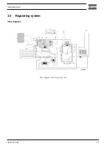
Page 17: ...Flow diagram of GA200 GA250 and GA315 60 Hz Instruction book 2920 1475 06 15 ...
Page 30: ...Menu flow for GA 90 up to GA 315 simplified example Instruction book 28 2920 1475 06 ...
Page 57: ...Dimension drawing of GA90 110 water cooled Instruction book 2920 1475 06 55 ...
Page 60: ...Dimension drawing of GA200 250 and GA315 60 Hz air cooled Instruction book 58 2920 1475 06 ...
Page 64: ...Compressor room example of GA 90 up to GA 160 water cooled Instruction book 62 2920 1475 06 ...
Page 76: ...Suspended solids Non soluble particles size 1 mm 10 ppm Instruction book 74 2920 1475 06 ...
Page 98: ...Filler and drain plugs on GA 200 up to GA 500 compressors Instruction book 96 2920 1475 06 ...
Page 102: ...Position of oil filter on GA 200 up to GA 500 Instruction book 100 2920 1475 06 ...
Page 133: ...Instruction book 2920 1475 06 131 ...
Page 134: ......
Page 135: ......


