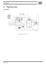
Flow diagram of air dryer on GA Full-Feature compressors
Air flow
Air drawn through filters (AF) and unloaders (UA) is compressed in compressor elements (E). Compressed
air and oil are discharged through check valves (CV) to air receiver/oil separators (AR) where oil is separated
from the compressed air. The air is blown through minimum pressure valves (Vp) to air coolers (Ca).
On GA Pack compressors, the cooled air is discharged through condensate traps (MTa) and outlet (AO)
towards the air net.
On GA Full-Feature compressors, the cooled air is discharged through condensate trap (MTa) and outlet (AO)
towards the air net via the integrated air dryer.
Check valves (CV) prevent blow-back of compressed air.
Minimum pressure valve (Vp) prevents the receiver pressure from dropping below a minimum pressure. The
valve has a built-in check valve.
Instruction book
16
2920 1475 06
Summary of Contents for GA110
Page 1: ...GA 90 GA 110 GA 132 GA 160 GA 200 GA 250 GA 315 ...
Page 2: ......
Page 17: ...Flow diagram of GA200 GA250 and GA315 60 Hz Instruction book 2920 1475 06 15 ...
Page 30: ...Menu flow for GA 90 up to GA 315 simplified example Instruction book 28 2920 1475 06 ...
Page 57: ...Dimension drawing of GA90 110 water cooled Instruction book 2920 1475 06 55 ...
Page 60: ...Dimension drawing of GA200 250 and GA315 60 Hz air cooled Instruction book 58 2920 1475 06 ...
Page 64: ...Compressor room example of GA 90 up to GA 160 water cooled Instruction book 62 2920 1475 06 ...
Page 76: ...Suspended solids Non soluble particles size 1 mm 10 ppm Instruction book 74 2920 1475 06 ...
Page 98: ...Filler and drain plugs on GA 200 up to GA 500 compressors Instruction book 96 2920 1475 06 ...
Page 102: ...Position of oil filter on GA 200 up to GA 500 Instruction book 100 2920 1475 06 ...
Page 133: ...Instruction book 2920 1475 06 131 ...
Page 134: ......
Page 135: ......


