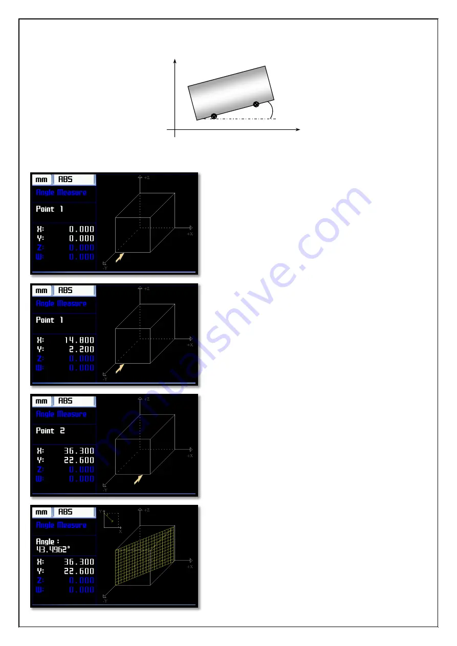
Atek ADR 50 Series Instruction Manual Download Page 39

[38] 


5.6.


Angle Measure 

The angle of the workpiece can be measured with Angle Measurement function. 


To  enter  the  the  Angle  Measure  Function,  press  "5"  button  while  on  the  function  screen  or  to  reach  the  "Angle 
Measure” with arrow keys then press "ENT" button. 


When the function startup the simulation screen will be 
open  like  a  the  side.  The  measuring  axis  should  be 
chosen  with  up  and  down  arrow  buttons.The  selected 
axis will be displayed as a white in the list on the left. 

To angle measurement of workpiece, from the edge of 
the  workpiece  must  be  taken  measurement  of  two 
reference points. 

When  the  function  opens  firstly  the  referance  point 
which  measurements  must  be  taken  is  presented  as 
representative. 


When insert the end of the reference point to one the 
“ENT” button is pressed. 


Simulation screen is updated for the reference point 2. 
Insert the end of the reference point is brought 2 and in 
order to show of angle the press "ENT" button. 


           X 

        Y 

Point 1 

Point 2 

Angle 

Workpiece 

Insert  the  end  of  the  2nd  reference  point  after  the 
“ENT”  button  is  pressed,  the  taper  angle of the  object 
will be shown on the screen. 


Summary of Contents for ADR 50 Series

Page 1: ...INSTRUCTION MANUAL HIGH PERFORMANCE LCD DIGITAL READOUTS Atek ADR 50 Series ...

Page 2: ... 9 3 2 1 Axis 10 3 2 2 Type 10 3 2 3 Resolution 10 3 2 4 Direction 10 3 2 5 Index 10 3 2 6 Hide 10 3 2 7 Degrees Minutes Secons Dmsec 10 3 3 Reference Zero Position 10 3 3 1 Electronic Reference Zero position of Scale 11 3 3 2 Mechanical Reference Mechanical Zeroing Position 12 3 4 Compensation Error Correction 13 3 4 1 Linear Compensation Linear Error Correction 13 3 4 2 Segmented Compensation Se...

Page 3: ...alculate on the axis 22 4 9 Recall the datum in memory 23 4 10 Sleep Mode 23 4 11 Axis Indicator Hold 24 4 12 Coordinate Point Memory 26 Route 1 26 Route 2 27 5 ADVANCED FUNCTIONS 28 5 1 Bolt Hole 29 5 2 Linear Pattern Hole Grid 31 5 3 Radius 33 5 4 Rectangular Pocket 35 5 5 Taper Measure 36 5 6 Angle Measure 38 5 7 EDM Erosion Depth Control Function 39 5 8 Outputs 41 Mode 0 42 Mode 1 43 Mode 2 43...

Page 4: ...lity to have been designed to meet all your needs New ADR 50 Manufacturing minimizes the time increases efficiency Manufacturing minimizes the time increases efficiency Improves the accuracy and sensitivity Improves the quality of the product being handled To move to the next position reduces 80 of the time spent Pays for itself in a short time with the benefits To obtain the highest performance u...

Page 5: ...ut signal OptionalPush Pull or TTL A B Z LineDriver A B Z A B Z Incremental Encoder Signals Weight 2 7 Kg Power supply 85 265 V AC 50 60Hz Storage Temperature 25 65 C Working Temperature 10 45 C Relative Humidity 20 85 No Condensation Dimension H x W x T 202mm x 320mm x 84mm Housing Aluminum Injection Housing Measurement Limits 99999 999 mm 99999 999 mm ...

Page 6: ...onal Multipication Substraction İşleButonu Division Square Root Equal Enter Sign Change Function Calculate Numeric Keys Recall Sleep Mode CosineFunction Sinus Function Tangant Function User Zeros Arrow Keys Clear Single Digit Deletion Inverse trigonometric functions Decimal Point Diameter Mode 2D Simulation Mode Advanced Function Menu Setup Instalation menu Calculator Memory Origin Theach Button E...

Page 7: ...gnetic field Do not use in humid environments and at high temperature The unit is always vertical position the operator can easily use the keyboard and indicators can easily mount to a height of Note 4 Axis ADR 10 4 Type DRO Back Panel View Open Collector Outputs Encoder Inputs RS 232 Connection USB connector Buzzer Voice output Power Input Power ON OFF Switch Fuse 1A WARNING During the installati...

Page 8: ...3 4 5 6 7 8 9 Signal A B V 0V A B Z Z Shield Pin Number 1 2 3 4 5 6 7 8 9 Signal A Emty V 0V Emty B Emty Z Shield Pin Number 1 2 3 4 5 6 7 8 9 Signal Boş Rx Tx Boş 0V Boş Boş Boş Shield Pin Number 1 2 3 4 5 6 7 8 9 Signal Out1 Out2 V GND Out3 Out4 Out5 Out6 Boş Pin Number 1 2 3 4 5 6 7 8 Signal NC COM NO Boş Boş Boş Boş Boş 1 2 3 4 5 6 7 8 9 1 2 3 4 5 6 7 8 9 1 2 3 4 5 6 7 8 9 1 2 3 4 5 6 7 8 9 ...

Page 9: ...enu it used 3 button 3 1 DRO DRO option is used for the mainly features of Digital Readout system the menu can be navigated with arrow keys up and down andit can be changed with right left arrow keys Numerical changes are made with the numerical buttons on the menu If numeric changes are saved if desired firstlyit must be saved with the ENT button After the numeric changes if it use ESC button to ...

Page 10: ...alue must be ON 3 1 7 Shrink After Plastic items are injected a certain amount of shrinkage and might pull them later Therefore before injection the mold size needed to grow at a certain rate Shrink function with this measure by entering the tolerance are captured To close the shrinkage the value should remain as a 1 0000000 For example To adjust shrinkage the 1000 of 5This value must be entered a...

Page 11: ... 4 Direction According to the movement of encoder the direction counting will be determined in this menu For positive direction counting the value must be entered 1 For negatif direction counting the value must be entered 1 3 2 5 Index if desired Zeroing Axis with index Z signal the value in menu should be made ON If the value in this menu is ON the Axis will be reset with each incoming index Z si...

Page 12: ...reference option is selected as Electronics pres ENT button when it comes Bul selected the axes values are displayed as a below When press ENT button the magnifying glass icon will be appeared next to the Axis which is electronic reference to be found Encoder is moved until to recieve the refernce signal the check icon will be appeared next to the Axis which get reference signal and axis will be r...

Page 13: ...he reference option is selected as Electronics pres ENT button when it comes Bul selected the axes values are displayed as a below When press ENT button the magnifying glass icon will be appeared next to the Axis which is electronic reference to be found Encoder is moved until to recieve the refernce signal The check iconwill be appeared next to the Axis which get reference signal and axis will be...

Page 14: ... a different error value for each axis Linear error is proportional increases with distance The value as called Correction Factor is entered for each axis Correction Factor can be calculated according to which value is showed how many mm at 1000 mm 1 meter on the display To active the Linear Compensation select the required axis to calibrate using X Y Z and press ENT then the selected Linear on th...

Page 15: ... on the screen the entered the value of distance between points of correction on the lenght line The entered the value of how many correction points on the number line Scroll to Start line and press ENT button then the sub window will be opened There are four lines in the sub window The current value of axis compensation to be applied is displayed on the first line if this value should be close to...

Page 16: ... correct value is entered to RealValue line on the menu In the above example 1 correction point is supposed to show 20 000 but as it shows 19 860 when this point is reached enter 20 on the RealValue line and save with ENT button when the correction point is saved 4 line measured value is displayed the next point is displayed on the Point line and the same process is repeated for this point The sam...

Page 17: ...the selected Restore on the parameter line and press ENT botton A query window will open Are you sure query Yes is selected Parameters will be restored In order to reset all parameters according to factory default the selected Fctry Rset on the parameter line and press ENT botton A query window will open Are you sure query Yes is selected The screen that opens Loading is displayed The ADR50 will r...

Page 18: ...displayed All programs have been erased 3 5 3 Factory Reset This menu is used to return factory settings of ADR50 Rotating the device to factory settings only the language bench type and motor parameters will not change In order to return to factory setting the selected Fctry Rset and press ENT botton A query window will open Are you sure query Yes is selected and ENT button to confirm The screen ...

Page 19: ... keyboard and I O is performed the tests The unit to be tested is selected with arrow button and starts to testing with ENT 3 7 1 Display Test The testing of LCD is performed with display test the display test is started by pressing ENT button on the display line After the Test the LCD screen respectively would be white red green and blue Thus in the case of any problems such as dead pixel problem...

Page 20: ...rked to be seen 3 7 3 I O Tests The testing of output units is performed by I O test The testing of output units is started by pressing ENT button on the I O line When press 0 EDM relay press 1 exit 1 press 2 exit 2 press 3 exit 3 press 4 exit 4 press 5 exit 5 press 6 exit 6 will be active If the same button is pressed again the output will be passive 3 8 Info It can be reached the information abo...

Page 21: ...emental Mode The working mode can be select by ABS INC button on the keypad Two different coordinate image system is supported Absolute Mode IncrementalMode The button is used for this process When each pressed the button the working mode will changed The mode of operation used in the upper left corner of the screen next to the measuring system is indicated 4 3 Axis Reset The value of axes can be ...

Page 22: ...entering W axis Select the axis to be entered by pressing a small window appears at the bottom right of the screen Value will appear on the display until press ENT ENT button is pressed the value is transferred to the axis 4 5 Setting Half Value of the Display The required axis value can be divided in half with the button on the keypad to perform this operation selected the desired axis then press...

Page 23: ... mode Dia Mode button is used for turn off the function The same button is also used for turn on this function In the example above the diameter mode which is open was closed To turn it on again Dia Mode button is used When diameter mode turn on the icon of diameter is located next to bench type the upper side on the LCD When the diameter mode turn off The icon changes and becomes an icon that mea...

Page 24: ...o intervene by 3 Persons when Indicators and buttons are disabled the process which incoming signals from scales is continued So if the system in sleep mode changing the location of the bench table detects this position of it transfers to new user Axis selection button is pressed it opens a small window at the bottom right and procedures that can be followed here The last is equal to or ENT button...

Page 25: ...indicator After frozen axis value if the machine was moving the tray table axis values can continue from the new position or you can continue the from frozen values To activate the function of Axis freeze function indicator press button of desired axis then the Hold button is pressed A lock icon appears next to the frozen axes Press again HOLD button and you can move the table The axis will be con...

Page 26: ... 25 Route 1 Route 2 There are two different ways to exit the function Even though Y Axis the position is changed continue from the hold value The new location is shown for changed of Y axis position ...

Page 27: ...ed to enter the coordinates again This function also can be used for lathe as a the memory of the team This function can be used in 2 different ways Route 1 Tables will be brought to the location stored Teach button is pressed the right hand side of the screen under appears Teach sign and beside a white box Write memory number and press ENT to save ...

Page 28: ...tton and coordinate values are entered with the numeric buttons Points of coordinate in memory is referenced by the Absolute operation mode It can be reached to points of coordinate by using buttons Tables will be brought to the location stored The Zero button is pressed and the desired memory record number is entered To go to this memory number the press ENT button The memory number shows in the ...

Page 29: ... a screen opens listing of functions as a following Among the options at the functions of menu can be moving with the arrow keys and when the desired options it can be entered in submenu with ENT button Shortcuts are available to move the desired option with numeric buttons 2 button is used to Radius menu ...

Page 30: ...lected plane is located in just below the entered a distance value which is processed axis to 0 point The radius of the circle is entered on the Diameter line The number of holes is entered on line Angle of first hole on Angle 1 line angle of last hole on Angle 2 line are entered and saved with ENT button When all data are entered the preview image on the left side will be updated according to thi...

Page 31: ...n arrow button is pressed the 2nd point in the simulation screen is displayed as white The new values is installed to Axes These axes are moved again until when the values reach to zero When it is zero reached the 2nd Point This point is processed too and to pass the 3rd point press ENT or the down arrow button All the points are processed in the same way and the function is exited with Esc button...

Page 32: ...n the first hole and the last hole of line and columns is indicated The suitable option selected here for processing If Mode option is selected as the length the distance between first hole to last hole on the L Row the distance between first column to last column on the L Column is entered If Mode option is selected as Step The distance betwen hole of rows on the L Row line the distance between h...

Page 33: ...mulation screen as a white the new values are loaded to the axis These axes are moved again until when the values reach to zero When it is zero reached the 2nd Point This point is processed too and to pass the 3rd point press ENT or the down arrow button All the points are processed in the same way and the function is exited with Esc button The View button can be used to pass the without simulatio...

Page 34: ...below the Plane line Tabs that you connect to the workpiece If it is request to give outer edges ovality the selected Quter on the Mode line If it is request to give inner edges ovality the selected Inner on the Mode line Enter radius of the circular area on the Radius line Enter tool diameter of workpiece on the Tool Dia line The angle of starting point process on Angle 1 line the angle of end pr...

Page 35: ... press ENT or down arrow button the second point is displayed on the simulation screen as a white The new values are loaded to the axis These axes are moved again until when the values reach to zero When it is zero reached the 2nd Point This point is processed too and to pass the 3rd point press ENT or the down arrow button All the points are processed in the same way and the function is exited wi...

Page 36: ...point to X axis is entered on the Center X line The distance of starting point center point to Y axis is entered on the Center Y line The size of discharged pool on the X axis length on the Size X line The size of discharged pool on the Y axis length on the Size Y line is entered The diameter of the tool used to workpiece is entered on the Tool Dia if the insert tipped tools is with radius the L 1...

Page 37: ...cated with white The value which to be When the function startup the simulation screen will be open like a the side The current position is shown with a yellow marker process axis is shown on left window If these values are zero its mean is reached the first point The first point is applied a process The down arrow or ENT button is used to pass to the next point Count of point and the total number...

Page 38: ...e end of the 2nd reference point after the ENT button is pressed the taper angle of the object will be shown on the screen If source is selected as Angle Enter the desired angle value using the numeric buttons In this case the diameter and height information of the cone is obtained dynamically with using the entered angle value and the information taken from Z axis If axis is selected as W The dia...

Page 39: ...list on the left To angle measurement of workpiece from the edge of the workpiece must be taken measurement of two reference points When the function opens firstly the referance point which measurements must be taken is presented as representative When insert the end of the reference point to one the ENT button is pressed Simulation screen is updated for the reference point 2 Insert the end of the...

Page 40: ...on on the top of screen If the EDM is selected from these modes The depth value of electrode is entered on the Depth line If the workpiece surface 0 is accepted the depth value should be entered minus The error which may arise from the electrode is entered on the Offset line For example due to the electrode wear caused in time the depth difference is adjusted by giving a value on the Offset line I...

Page 41: ... yellow marker The yellow line shows the value of depth the pink line is depth offset value Operation is made according to value of pink The axis values shows on the left side at the same time The active axis white others are blue During the function active the red led which next to image of EDM is blinking The action is displayed on the screen until Axis reaches the desired value The electrode mo...

Page 42: ...at it was pulled on the right side of axis The relay remains in the same position until the axis value which to be process reach to value of Offset Depth When the axis value is passed the value of the offset depth and the icon at right of the axis disappears Axis value falls below the value of the offset depth again the relay pulls again and the icon appears If desired the function is closed the f...

Page 43: ...ue is entered on the Offset line this value is added to the Set value andthe scenario is applied according to this total value Top value of hysterical is entered on the UpHystr line When Axis value increase the value entered here is added Set Offset value Lower value of hysterical is entered on the DwnHystr line When Axis valuedecreased the value entered here is removed Set Offset value andthe sce...

Page 44: ...ation is not entered in the output remains active if the duration is entered the output is remains active during the entered time and then switches to passive position The output remains active unless it comes buton reset the axis or reset the signal Optionally histeric and offset values can be entered Mode 3 Axis value reaches Set 1 value axis value will be locked and the output is active The out...

Page 45: ...sensor of sensor Optionally histeric and offset values can be entered Mode 5 When Axis value becomes between the values of Set 1 and Set 2 the output is active Set 2 value is used only this mode If the duration is entered the output is remains active during the entered time and axis value remains in the locked position End of the duration the output becomes passive and Axis value is reset Optional...

Page 46: ...be selected and Set 1 value is given 10 But the output will not be active until the total value of X Axis is 17 in order to offset value is given 5 and upper rate of hysteresis is 2 After X Axis value is passed 17 the 3 number of output will be active Output again in order to be passive the reset signal must be sent to X Axis from sensor or Axis reset button ...

Page 47: ...reen with ESC button The screen displays the values of orjin 0 The user resets the values of an axis and processing the point by moving the tray The other orjin value is passed with down arrow butons and the values is reseted by moving of the tray At this point are processed The same process is repeated for all points 2D simulation screen can be displayed by pressing View button The processed poin...

Page 48: ...SOR TECHNOLOGY AS Tuzla Kimya Sanayicileri Organize Sanayi Bolgesi Melek Aras Bulvari No 67 TR 34956 Tuzla Istanbul TURKEY Tel 90 216 399 44 04 Fax 90 216 399 44 02 Web www ateksensor com E Mail info ateksensor com ...

Reviews: