EF600 Instruction Manual
Asymptote Ltd.
St John’s Innovation Centre, Cowley Road, Cambridge, CB4 0WS, UK
Tel: +44 1223 421161, Fax: +44 1223 421166, E-mail: [email protected]
4
List of Figures
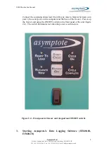
Figure 3 – Desktop shortcut icon ................................................................................... 9
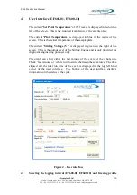
Figure 4 – User interface .............................................................................................. 10
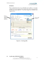
Figure 4.1 – Freezing profile ....................................................................................... 11
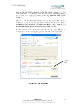
Figure 4.2 – Log file names ......................................................................................... 12
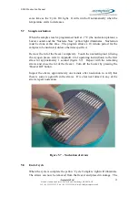
Figure 5.4 – Straws positioned in sample plate ........................................................... 14
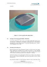
Figure 5.7 – Nucleation of straws ................................................................................ 15
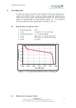
Figure 6.1 – Pre-programmed human embryo freezing cycle ..................................... 17
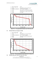
Figure 6.2 – Pre-programmed human oocyte freezing cycle ....................................... 18
Figure 6.3 – Pre-programmed human blastocyst freezing cycle .................................. 18
Figure 6.4 – Pre-programmed human embryonic stem cell freezing cycle ................. 19
Figure 6.5 – Pre-programmed human sperm freezing cycle ........................................ 19
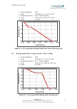
Figure 6.6 – Pre-programmed human spermatozoa non-linear freezing cycle ............ 20
Figure A2.1 – Installation box 1 .................................................................................. 24
Figure A2.2 – Installation box 2 .................................................................................. 25
Figure A2.3 – Installation box 3 .................................................................................. 25
Figure A2.4 – Installation box 4 .................................................................................. 26
Figure A2.5 – Installation box 5 .................................................................................. 26
Figure A2.6 – Installation box 6 .................................................................................. 27
Figure A2.7 – Installation box 7 .................................................................................. 27
Figure A2.8 – Installation box 8 .................................................................................. 28

