


ASUS Z9PE-D8 WS
2-9
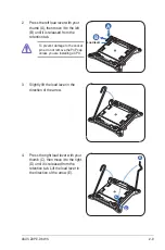
2. Press the left load lever with your
thumb (A), then move it to the left
(B) until it is released from the
retention tab.
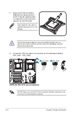
To prevent damage to the socket
pins, do not remove the PnP cap
unless you are installing a CPU.
B
A
E
D
C
4. Press the right load lever with your
thumb (C), then move it to the right
(D) until it is released from the
retention tab. Lift the load lever in
the direction of the arrow (E).
3. Slightly lift the load lever in the
direction of the arrow.
Load lever
Summary of Contents for Z9PE-D8 WS
Page 1: ...Motherboard Z9PE D8 WS ...
Page 22: ...1 8 Chapter 1 Product introduction ...
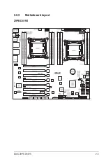
Page 27: ...ASUS Z9PE D8 WS 2 5 2 2 3 Motherboard layout Z9PE D8 WS ...
Page 51: ...ASUS Z9PE D8 WS 2 29 2 9 Connectors 2 9 1 Rear panel connectors ...
Page 64: ...2 42 Chapter 2 Hardware information ...
Page 195: ...ASUS Z9PE D8 WS 6 29 9 Click Finish to complete the installation ...
Page 222: ...Appendix summary A ASUS Z9PE D8 WS A 1 Z9PE D8 WS block diagram A 3 ...
Page 223: ...ASUS Z9PE D8 WS A 3 A 1 Z9PE D8 WS block diagram ...


