


4-12
Chapter 4: BIOS setup
CPU Ratio [Auto]
This item allows users adjust the maximum non-turbo CPU ratio. Use the <+> and
<-> keys to adjust the value. The values range from 12 to 57 with 1 interval.
CPU1 Voltage [Auto]
Use the <+> and <-> keys to adjust the value. The values range from 0.800V to
1.520V with 0.005V interval.
CPU1 VSA Voltage [Auto]
Use the <+> and <-> keys to adjust the value. The values range from 0.800V to
1.520V with 0.005V interval.
CPU2 Voltage [Auto]
Use the <+> and <-> keys to adjust the value. The values range from 0.800V to
1.520V with 0.005V interval.
CPU2 VSA Voltage [Auto]
Use the <+> and <-> keys to adjust the value. The values range from 0.800V to
1.520V with 0.005V interval.
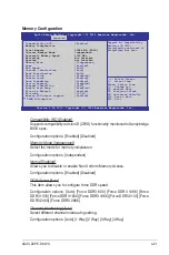
DRAM Voltage (CHA, CHB) [Auto]
Use the <+> and <-> keys to adjust the value. The values range from 1.20V to
1.52V with 0.005V interval.
DRAM Voltage (CHC, CHD) [Auto]
Use the <+> and <-> keys to adjust the value. The values range from 1.20V to
1.52V with 0.005V interval.
DRAM Voltage (CHE, CHF) [Auto]
Use the <+> and <-> keys to adjust the value. The values range from 1.20V to
1.52V with 0.005V interval.
DRAM Voltage (CHG, CHH) [Auto]
Use the <+> and <-> keys to adjust the value. The values range from 1.20V to
1.52V with 0.005V interval.
Clock Spread Spectrum [Disabled]
[Disabled] Enhances BCLK overclocking ability.
[Enabled] For [EMI] control.
Summary of Contents for Z9PE-D8 WS
Page 1: ...Motherboard Z9PE D8 WS ...
Page 22: ...1 8 Chapter 1 Product introduction ...
Page 27: ...ASUS Z9PE D8 WS 2 5 2 2 3 Motherboard layout Z9PE D8 WS ...
Page 51: ...ASUS Z9PE D8 WS 2 29 2 9 Connectors 2 9 1 Rear panel connectors ...
Page 64: ...2 42 Chapter 2 Hardware information ...
Page 195: ...ASUS Z9PE D8 WS 6 29 9 Click Finish to complete the installation ...
Page 222: ...Appendix summary A ASUS Z9PE D8 WS A 1 Z9PE D8 WS block diagram A 3 ...
Page 223: ...ASUS Z9PE D8 WS A 3 A 1 Z9PE D8 WS block diagram ...


