


ASUS Z10PH-D16
2-33
8.
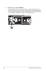
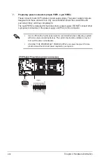
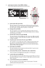
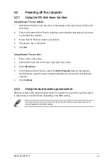
System panel connector (16-pin PANEL1 [White])
This connector supports several chassis-mounted functions.
A. System power LED (2-pin PLED)
This 2-pin connector is for the system power LED. Connect the chassis power
LED cable to this connector. The system power LED lights up when you turn on
the system power, and blinks when the system is in sleep mode.
B. Message LED (2-pin MLED)
This 2-pin connector is for the message LED cable that connects to the front
message LED. The message LED is controlled by Hardware monitor to indicate
an abnormal event occurance.
C. Hard disk drive activity LED (2-pin HDDLED)
This 2-pin connector is for the HDD Activity LED. Connect the HDD Activity LED
cable to this connector. The IDE LED lights up or flashes when data is read from
or written to the HDD.
D. Proprietary power button/soft-off button (2-pin PWRSW)
This connector is for the system power button. Pressing the power button turns
the system on or puts the system in sleep or soft-off mode depending on the
BIOS settings. Pressing the power switch for more than four seconds while the
system is ON turns the system OFF.
E. Reset button (2-pin RESET)
This 2-pin connector is for the chassis-mounted reset button for system reboot
without turning off the system power.
F. LAN activity LED (2-pin LAN1_LINKACTLED, LAN2_LINKACTLED)
These connectors are for Gigabit LAN activity LEDs on the front panel.
G. Locator LED (2-pin LOCATORLED)
This 2-pin connector is for the Locator LED on the front panel. When you connect
the Locator LED cable to this 2-pin connector, the LED lights up when the Locator
button is pressed.
H. Locator Button/Switch (2-pin LOCATORBTN#)
This 2-pin connector is for the Locator button on the front panel. This button
queries the state of the system locator.
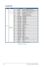
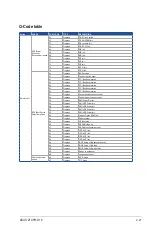
Summary of Contents for Z10PH-D16
Page 1: ...Z10PH D16 Server Motherboard User Guide ...
Page 14: ...xiv ...
Page 22: ...2 4 Chapter 2 Hardware information 2 2 3 Z10PH D16 Motherboard layout ...
Page 58: ...2 40 Chapter 2 Hardware information ...
Page 62: ...3 4 Chapter 3 Powering up ...
Page 152: ...5 38 Chapter 5 RAID configuration ...
Page 180: ...A 2 Appendix A Reference information A 1 Z10PH D16 block diagram ...