


Chapter 4: Motherboard information
4-8
4.3.2
Internal connectors
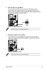
1. Floppy disk drive connector (34-1 pin FLOPPY1)
This connector is for the provided Floppy Disk Drive (FDD) signal cable.
Insert one end of the cable to this connector, then connect the other end to
the signal connector at the back of the floppy disk drive.
Pin 5 on the connector is removed to prevent incorrect cable connection when
using a FDD cable with a covered Pin 5.
®
P5BP-E/4L
P5BP-E/4L F
loppy Disk Drive Connector
NOTE:
Orient the red markings on
the floppy ribbon cable to PIN 1.
PIN1
FLOPPY
Summary of Contents for TS300-E5
Page 1: ...TS300 E5 Intel Xeon 3000 3200 Series LGA775 Pedestal 5U Server ...
Page 12: ...xii ...
Page 76: ...Chapter 3 Installation option 3 10 ...
Page 126: ...5 34 Chapter 5 BIOS setup ...
Page 186: ...6 60 Chapter 6 RAID configuration ...


