


2-25
ASUS TS300-E5
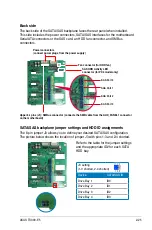
Back side
The back side of the SATA/SAS backplane faces the rear panel when installed.
This side includes the power connectors, SATA/SAS interfaces for the motherboard
Serial ATA connectors or the SAS card, an HDD fan connector, and SMBus
connectors.
Fan connector (for HDD fan)
Power connectors
(connect power plugs from the power supply)
Upper 6-1 pins (J1): SMBus connector (connects the SMB cable from the AUX_PANEL1 connector
on the motherboard)
SAS Port 0
SAS Port 1
SAS Port 2
SAS Port 3
SATA/SAS backplane jumper settings and HDD ID assignments
The 6-pin jumper J3 allows you to define your desired SATA/SAS configuration.
The picture below shows the location of jumper J3 with pins 1-3 and 2-4 shorted.
Refer to the table for the jumper settings
and the appropriate ID# for each SATA
HDD bay.
J3 setting
(1-3 shorted, 2-4 shorted)
Device
SATA/SAS ID
Drive Bay 1
ID0
Drive Bay 2
ID1
Drive Bay 3
ID2
Drive Bay 4
ID3
SAS HDD Activity LED
connector (for PX4 model only)
Summary of Contents for TS300-E5
Page 1: ...TS300 E5 Intel Xeon 3000 3200 Series LGA775 Pedestal 5U Server ...
Page 12: ...xii ...
Page 76: ...Chapter 3 Installation option 3 10 ...
Page 126: ...5 34 Chapter 5 BIOS setup ...
Page 186: ...6 60 Chapter 6 RAID configuration ...


