


1-22
Chapter 1: Motherboard Information
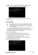
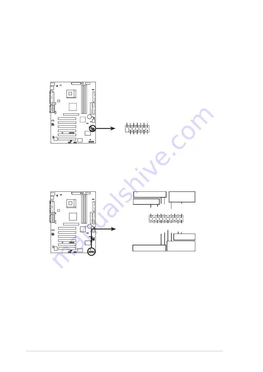
16. System panel connector (20-pin PANEL1)
This connector accommodates several system front panel functions.
P4SE
®
P4SE System Panel Connectors
*
Requires an ATX power supply.
PLED
Ground
MLED
PWR
+5 V
+5V
Speaker
Speaker
Connector
Power LED
Ground
+5 V
Reset SW
SMI Lead
Message LED
ExtSMI#
Ground
Reset
Ground
Ground
ATX Power
Switch*
Keylock
Ground
Keyboard Lock
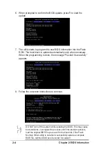
15. Smart card reader connector (14-1 pin SMARTCON1) (optional)
This connector accommodates a Smart Card Reader that allows you
to conveniently make transactions such as financial, health care,
telephony, or traveling services through a Smart Card user interface
software.
P4SE
®
P4SE Smartcard
SMARTCON1
NC
SCPWR
NC
NC
NC2
VCC
GND
SCIO
SCRRES#
NC
SCRCLK
1
NC
SCRREST
•
System Power LED Lead (3-1 pin PLED)
This 3-1 pin connector connects to the system power LED. The LED
lights up when you turn on the system power, and blinks when the
system is in sleep mode.
•
System Warning Speaker Lead (4-pin SPEAKER)
This 4-pin connector connects to the case-mounted speaker and
allows you to hear system beeps and warnings.
Summary of Contents for P4SE
Page 1: ...Motherboard P4SE User Guide ...
Page 34: ...1 24 Chapter 1 Motherboard Information ...
Page 60: ...2 26 Chapter 2 BIOS Information ...
Page 70: ...3 10 Chapter 3 Starting Up ...


