


1-16
Chapter 1: Motherboard Information
4.
Chassis open alarm lead (4-1 pin CHASSIS)
This lead is for a chassis designed with intrusion detection feature.
This requires an external detection mechanism such as a chassis
intrusion sensor or microswitch. When you remove any chassis
component, the sensor triggers and sends a high-level signal to this
lead to record a chassis intrusion event.
If you do not wish to use the chassis intrusion lead, place a jumper cap
over the pins labeled “Chassis Signal” and “Ground” to close the
circuit.
P4SE
®
P4SE Chassis Alarm Lead
CHASSIS1
+5VSB_MB
Chassis Signal
GND
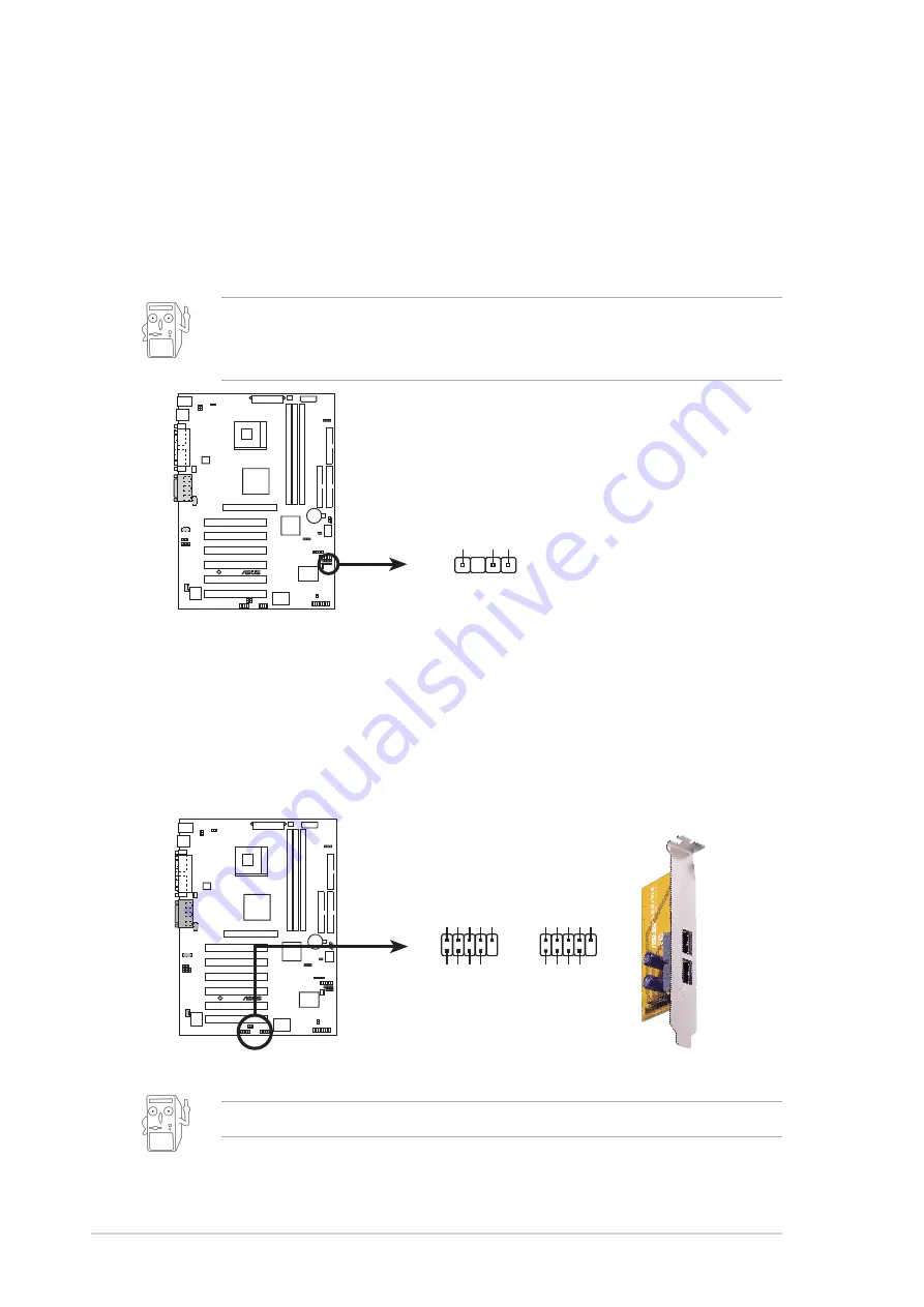
5.
USB headers (two 10-1 pin USB2, USB3)
If the USB port connectors on the rear panel are inadequate, two USB
headers are available for additional USB port connectors. Connect the
bundled 2-port USB connector set to this header and mount the USB
bracket to an open slot in the chassis.
P4SE
®
P4SE Front Panel USB Headers
USB2
USB3
1
5
6
10
USB Power
USBP2–
USBP2+
GND
OC1#
USB Power
USBP3–
USBP3+
GND
1
5
6
10
USB Power
USBP2–
USBP2+
GND
OC1#
USB Power
USBP3–
USBP3+
GND
The two-port USB connector is not included in the package.
Summary of Contents for P4SE
Page 1: ...Motherboard P4SE User Guide ...
Page 34: ...1 24 Chapter 1 Motherboard Information ...
Page 60: ...2 26 Chapter 2 BIOS Information ...
Page 70: ...3 10 Chapter 3 Starting Up ...


