


5-2
Chapter 5: Multiple GPU technology support
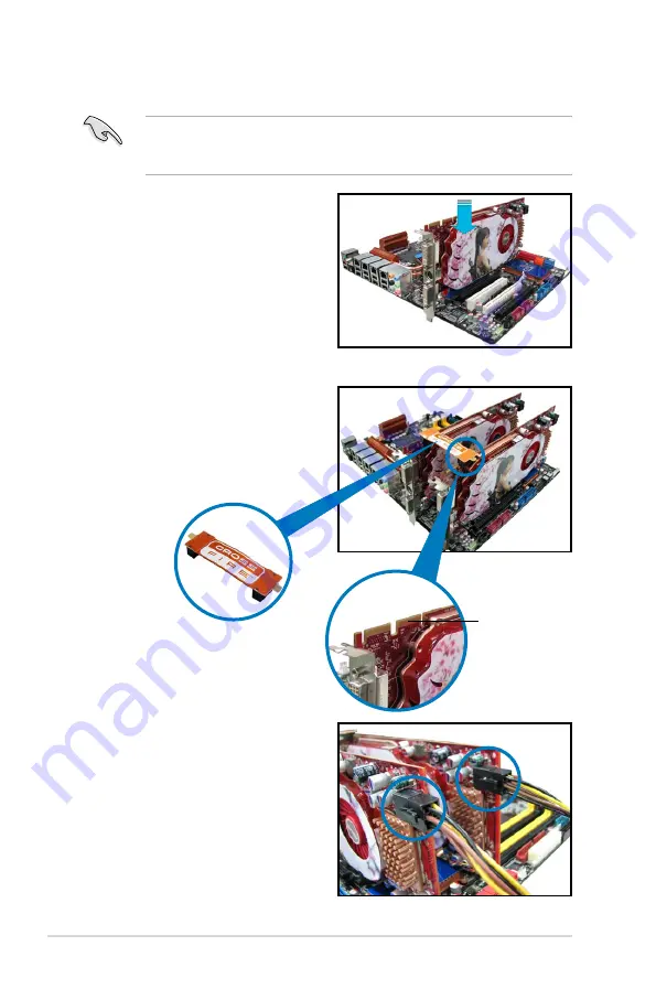
5. Connect two independent auxiliary
power sources from the power
supply to the two graphics cards
separately.
6. Connect a VGA or a DVI cable to the
graphics card.
4. Align and firmly insert the
CrossFireX bridge connector to the
goldfingers on each graphics card.
Ensure that the connector is firmly
in place.
5.1.3
Installing CrossFireX graphics cards
The following pictures are for reference only. The graphics cards and the
motherboard layout may vary with models, but the installation steps remain the
same.
1. Prepare two CrossFireX-ready
graphics cards.
2. Insert the two graphics card into the
PCIEX16 slots.
3. Ensure that the cards are properly
seated on the slots.
Goldfingers
CrossFireX bridge
Summary of Contents for MAXIMUS IV GENE-Z
Page 1: ...Motherboard Maximus IV GENE Z ...
Page 18: ...xviii ...
Page 30: ...1 10 Chapter 1 Product Introduction ...
Page 69: ...A B 1 2 3 2 3 2 CPU installation ASUS Maximus IV GENE Z 2 37 ...
Page 70: ...C B A 5 6 4 2 38 Chapter 2 Hardware information ...
Page 73: ...1 2 3 To remove a DIMM 2 3 4 DIMM installation B A ASUS Maximus IV GENE Z 2 41 ...
Page 76: ...2 3 6 ATX Power connection 1 2 OR OR 2 44 Chapter 2 Hardware information ...
Page 77: ...2 3 7 SATA device connection OR 2 OR 1 ASUS Maximus IV GENE Z 2 45 ...
Page 83: ...Connect to 5 1 channel Speakers Connect to 7 1 channel Speakers ASUS Maximus IV GENE Z 2 51 ...
Page 86: ...2 54 Chapter 2 Hardware information ...
Page 125: ...ROG Maximus IV GENE Z 3 37 3 8 2 Asus SPD Information This item displays the SPD information ...
Page 138: ...3 50 Chapter 3 BIOS setup ...
Page 176: ...4 36 Chapter 4 Software support ...