


3-30
Chapter 3: BIOS setup
3.6
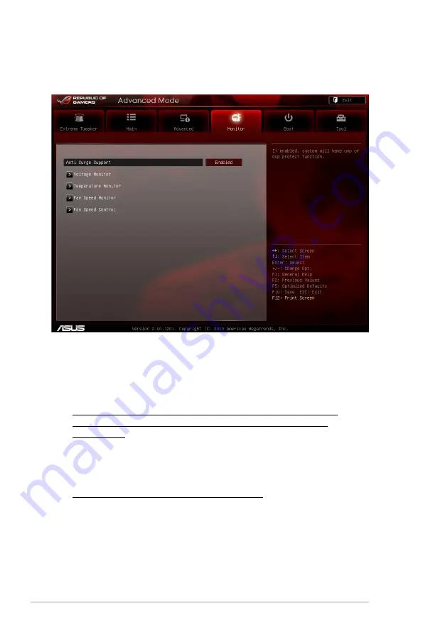
Monitor menu
The Monitor menu displays the system temperature/power status, and allows you
to change the fan settings.
Anti Surge Support [Enabled]
This item allows you to enable or disable the Anti Surge function.
Configuration options: [Disabled] [Enabled]
Voltage Monitor
CPU Voltage; 3.3V Voltage; 5V Voltage; 12V Voltage; DRAM Voltage;
PCH Voltage; PCH Voltage; VCCSA/IO Voltage; CPU PLL Voltage;
IGPU Voltage
The onboard hardware monitor automatically detects the voltage output
through the onboard voltage regulators.
Temperature Monitor
CPU Temperature; MB Temperature [xxxºC/xxxºF]
The onboard hardware monitor automatically detects and displays the CPU,
and motherboard. Select [Ignored] if you do not wish to display the detected
temperatures.
Summary of Contents for MAXIMUS IV GENE-Z
Page 1: ...Motherboard Maximus IV GENE Z ...
Page 18: ...xviii ...
Page 30: ...1 10 Chapter 1 Product Introduction ...
Page 69: ...A B 1 2 3 2 3 2 CPU installation ASUS Maximus IV GENE Z 2 37 ...
Page 70: ...C B A 5 6 4 2 38 Chapter 2 Hardware information ...
Page 73: ...1 2 3 To remove a DIMM 2 3 4 DIMM installation B A ASUS Maximus IV GENE Z 2 41 ...
Page 76: ...2 3 6 ATX Power connection 1 2 OR OR 2 44 Chapter 2 Hardware information ...
Page 77: ...2 3 7 SATA device connection OR 2 OR 1 ASUS Maximus IV GENE Z 2 45 ...
Page 83: ...Connect to 5 1 channel Speakers Connect to 7 1 channel Speakers ASUS Maximus IV GENE Z 2 51 ...
Page 86: ...2 54 Chapter 2 Hardware information ...
Page 125: ...ROG Maximus IV GENE Z 3 37 3 8 2 Asus SPD Information This item displays the SPD information ...
Page 138: ...3 50 Chapter 3 BIOS setup ...
Page 176: ...4 36 Chapter 4 Software support ...