Asus Crosshair V Formula Series User Manual Download Page 26

1-6

Chapter 1: Product Introduction

Extreme.Tweaker..

One.stop.performance.tuning.shop


Extreme Tweakers is the one stop shop to fine-tune your system to optimal 

performance. No matter if you're looking for frequency adjustment, over-voltage 

options, or memory timing settings, they're all here! 

Voltiminder.LED..

Friendly.reminder.on.Voltage.Settings.

In the pursuit of extreme performance, overvoltage adjustment is critical but 

risky. Acting as the "red zone" of a tachometer, the Voltiminder LED displays the 

voltage status for CPU, PCH, and Memory in a intuitive color-coded fashion. The 

voltiminder LED allows quick voltage monitoring for overclockers.

COP.EX..

Maximum OC with confidence with burn proof protection to chipsets and GPU!


The COP EX allows overclockers to increase chipset voltage without the worries 

of overheating. It can also be used to monitor and save an overheating GPU. 

The COP EX allows more freedom and less constraint for maximum performance 

achievement.

Loadline.Calibration..

Optimal power boost for extreme CPU overclocking! 

Maintaining ample voltage support for the CPU is critical during overclocking. 

The Loadline Calibration ensures  stable and optimal CPU voltage under heavy 

loading. It helps overclockers enjoy the motherboard's ultimate OC capabilities and 

benchmark scores.

Onboard.Switches..

No more shorting pins or moving jumpers 

With an easy press during overclock, this exclusive onboard switch allows gamer 

to effortlessly fine-tune the performance without having to short the pins or moving 

jumpers!

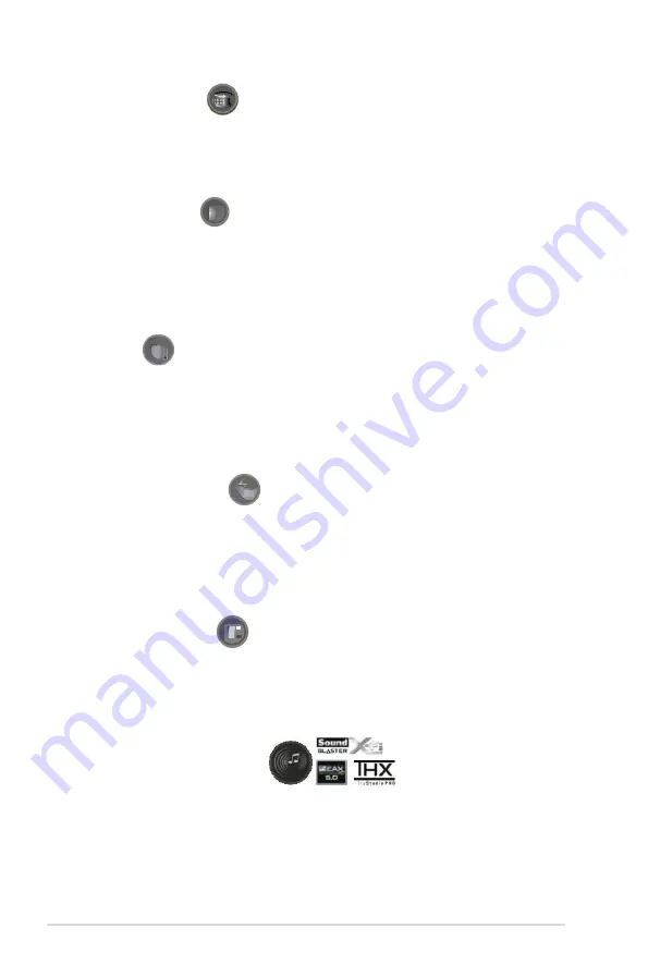
SupremeFX.X-Fi.2.Built-in..

Play.with.ultra-real.cinematic.in-game.surround.sound!

SupremeFX X-Fi 2 delivers incredible gaming audio experiences to ROG die 

hards. It features EAX 5.0 and OpenAL for ultra-real cinematic in-game audio. 

It even comes with THX TruStudio Pro, which makes games, music and movies 

sound way better! SupremeFX X-Fi 2 also implements gold-plated jacks and high 

quality capacitors to ensure high definition adventures in audio.

Summary of Contents for Crosshair V Formula Series

Page 1: ...Motherboard Crosshair V Formula Series ...

Page 2: ...CHANTABILITY OR FITNESS FOR A PARTICULAR PURPOSE IN NO EVENT SHALL ASUS ITS DIRECTORS OFFICERS EMPLOYEES OR AGENTS BE LIABLE FOR ANY INDIRECT SPECIAL INCIDENTAL OR CONSEQUENTIAL DAMAGES INCLUDING DAMAGES FOR LOSS OF PROFITS LOSS OF BUSINESS LOSS OF USE OR DATA INTERRUPTION OF BUSINESS AND THE LIKE EVEN IF ASUS HAS BEEN ADVISED OF THE POSSIBILITY OF SUCH DAMAGES ARISING FROM ANY DEFECT OR ERROR IN ...

Page 3: ... 1 1 1 2 Package contents 1 1 1 3 Special features 1 2 1 3 1 Product highlights 1 2 1 3 2 ROG ThunderBolt LAN Audio Combo 1 3 1 3 3 ROG Intelligent Performance Overclocking features 1 4 1 3 4 ASUS special features 1 7 Chapter 2 Hardware information 2 1 Before you proceed 2 1 2 2 Motherboard overview 2 2 2 2 1 Motherboard layout 2 2 2 2 2 Layout contents 2 3 2 2 3 Central Processing Unit CPU 2 4 2 ...

Page 4: ...the computer 2 51 2 5 1 Using the OS shut down function 2 51 2 5 2 Using the dual function power switch 2 51 Chapter 3 BIOS setup 3 1 Knowing BIOS 3 1 3 2 BIOS setup program 3 1 3 2 1 EZ Mode 3 2 3 2 2 Advanced Mode 3 3 3 3 Extreme Tweaker menu 3 5 3 4 Main menu 3 12 3 4 1 System Language English 3 12 3 4 2 System Date Day xx xx xxxx 3 12 3 4 3 System Time xx xx xx 3 12 3 4 4 Security 3 13 3 5 Adv...

Page 5: ...SUS BIOS Updater 3 45 Chapter 4 Software support 4 1 Installing an operating system 4 1 4 2 Support DVD information 4 1 4 2 1 Running the support DVD 4 1 4 2 2 Drivers menu 4 2 4 2 3 Utilities menu 4 3 4 2 4 Make disk menu 4 4 4 2 5 Manual menu 4 4 4 2 6 Video menu 4 5 4 2 7 ASUS Contact information 4 5 4 2 8 Other information 4 6 4 3 Software information 4 8 4 3 1 ASUS AI Suite II 4 8 4 3 2 Tool ...

Page 6: ... Windows 4 43 4 5 3 Installing the RAID driver during Windows OS installation 4 44 4 5 4 Using a USB floppy disk drive 4 45 Chapter 5 Multiple GPU technology support 5 1 ATI CrossFireX technology 5 1 5 1 1 Requirements 5 1 5 1 2 Before you begin 5 1 5 1 3 Installing CrossFireX graphics cards 5 2 5 1 4 Installing the device drivers 5 3 5 1 5 Enabling the ATI CrossFireX technology 5 3 5 2 NVIDIA SLI...

Page 7: ...re of the following measures Reorient or relocate the receiving antenna Increase the separation between the equipment and receiver Connect the equipment to an outlet on a circuit different from that to which the receiver is connected Consult the dealer or an experienced radio TV technician for help The use of shielded cables for connection of the monitor to the graphics card is required to assure ...

Page 8: ...3 Protection requirements for health and safety as in Article 3 1a Testing for electric safety according to EN 60950 Protection requirements for electromagnetic compatibility in Article 3 1b Testing for electromagnetic compatibility in EN 301 489 1 EN 301 489 17 Effective use of the radio spectrum as in Article 3 2 Radio test suites according to EN 300 328 2 CE Marking CE marking for devices witho...

Page 9: ...erty is not permitted In the departments listed below for the entire 2 4 GHz band Maximum authorized power indoors is 100mW Maximum authorized power outdoors is 10mW Departments in which the use of the 2400 2483 5 MHz band is permitted with an EIRP of less than 100mW indoors and less than 10mW outdoors 01 Ain 02 Aisne 03 Allier 05 Hautes Alpes 08 Ardennes 09 Ariège 11 Aude 12 Aveyron 16 Charente 2...

Page 10: ...ng RF exposure compliance Operation is subject to the following two conditions This device may not cause interference and This device must accept any interference including interference that may cause undesired operation of the device To prevent radio interference to the licensed service i e co channel Mobile Satellite systems this device is intended to be operated indoors and away from windows to...

Page 11: ...set to the correct voltage in your area If you are not sure about the voltage of the electrical outlet you are using contact your local power company If the power supply is broken do not try to fix it by yourself Contact a qualified service technician or your retailer The optical S PDIF is an optional component may or may not be included in your motherboard and is defined as a CLASS 1 LASER PRODUC...

Page 12: ...be used in environments with ambient temperatures between 5ºC 41ºF and 40ºC 104ºF Place the product on a stable surface If you encounter technical problems with the product contact a qualified service technician or your retailer DO NOT throw the motherboard in municipal waste This product has been designed to enable proper reuse of parts and recycling This symbol of the crossed out wheeled bin ind...

Page 13: ...e contains the following parts Chapter 1 Product introduction This chapter describes the features of the motherboard and the new technology it supports Chapter 2 Hardware information This chapter lists the hardware setup procedures that you have to perform when installing system components It includes description of the switches jumpers and connectors on the motherboard Chapter 3 BIOS setup This c...

Page 14: ... symbols used throughout this manual Typography Bold text Indicates a menu or an item to select Italics Used to emphasize a word or a phrase Key Keys enclosed in the less than and greater than sign means that you must press the enclosed key Example Enter means that you must press the Enter or Return key Key1 Key2 Key3 If you must press two or more keys simultaneously the key names are linked with ...

Page 15: ...m may only recognize less than 3GB Hence a total installed memory of less than 3GB is recommended Expansion Slots 3 x PCIe 2 0 x16 slots dual x16 x16 x8 x8 1 x PCIe 2 0 x16 x4 speed 1 x PCIe 2 0 x1 1 x PCI 2 2 Multi GPU Technology Supports 3 Way NVIDIA SLI AMD CrossFireX Technology Storage SB950 South Bridge 6 x SATA 6Gb s ports with RAID 0 1 5 10 red ASMedia controllers 1 x SATA 6Gb s port red 1 ...

Page 16: ... Overheat Protection EX Voltiminder LED ASUS C P R CPU Parameter Recall Other Special Features Core Unlocker ASUS Fan Xpert ASUS Q Connector ASUS Q Shield ASUS Q LED CPU DRAM VGA Boot Device LEDs Ai Charger ASUS EZ Flash 2 ASUS MyLogo 3 BIOS Features 32Mb Flash ROM UEFI BIOS PnP DMI2 0 WfM2 0 SM BIOS 2 5 ACPI2 0a Multi Language BIOS Manageability WOL by PME WOR by PME PXE Back Panel I O Ports 1 x ...

Page 17: ...ATX 12V power connector 1 x 4 pin ATX 12V power connector 1 x EZ Plug connector 4 pin Molex Power connector 1 x En Dis able Clr CMOS header 1 x CPU Level Up button 1 x ROG Connect switch 1 x START Power on button 1 x RESET button 1 x Go button 1 x Audio front panel AAFP header 1 x System panel connector Software Drivers Sound Blaster X Fi 2 Utility Kaspersky Anti Virus DAEMON Tools Pro Standard RO...

Page 18: ...24 bit TI 6120A2 high fidelity headphone amplifier Digital to Analog Converter 120dB Max 192kHz 24 bit Analog to Digital Converter 114dB Max 192KHz 24 bit Supports 3 Headphone Impedance Gain Modes up to 300 ohms Fine tuned Game Genre EQ Profiles Xear Surround Headphone Xear SingFX Equalizer Environment Effects FlexBass Smart Volume Virtual Speaker Shifter DS3D GX 1 0 OpenAL Front panel audio conne...

Page 19: ...1 Chapter 1 Product introduction This chapter describes the motherboard features and the new technologies it supports ...

Page 20: ...ROG Crosshair V Formula Chapter summary 1 1 1 Welcome 1 1 1 2 Package contents 1 1 1 3 Special features 1 2 ...

Page 21: ...oard package for the following items Motherboard ROG Crosshair V Formula Card ROG ThunderBolt Cables 1 x ROG Connect cable 1 x CrossFire Cable 1 x SLI Cable 3 x 2 in 1 SATA 6G cables 1 x USB to USB cable for ThunderBolt Accessories 1 x 2 in 1 ASUS Q Connector Kit 1 x 3 Way SLI Bridge 1 x Cable Ties Pack 1 x ROG Theme Label 1 x 12 in 1 ROG SATA Cable Label 1 x I O Shield Application DVD ROG motherb...

Page 22: ...ith up to 8 core native CPU cores and delivers better overclocking capabilities with less power consumption It features AMD Turbo CORE Technology 2 0 and accelerates data transfer rate up to 5200MT s via HyperTransport 3 0 based system bus This motherboard also supports AMD CPUs in the new 32nm manufacturing process AMD 990FX Chipset AMD 990FX Chipset is designed to support up to 5 2GT s HyperTran...

Page 23: ...OG ThunderBolt s high sound quality and built in amp gamers can discover the enemy s position much easier and react earlier making it just like another weapon in a gamer s arsenal With fine tuned background sound effects for popular game types and Xear 3D Surround tech ROG ThunderBolt lets you hear better and win easier Dedicated NPU Play FASTER Even with a high end CPU and GPU FPS and MMORPGs can...

Page 24: ...system to a notebook through a USB cable allowing you to view real time POST code and hardware status readouts on your notebook as well as make on the fly parameter adjustments at a purely hardware level Diagram power reset button flash BIOS through notebook Refer to page 2 29 for details GameFirst The speed you need to pwn Low Internet latency allows you to frag more and get fragged less That s w...

Page 25: ... ROG offers a whole new UEFI BIOS feature to handle the demands of an overclocking experience Rampage III Black Edition features ROG BIOS Print which allows users to easily share their BIOS settings to others with the press of a button The days of using a camera to take BIOS screenshot are over ProbeIt Get all hands on with hardware based overclocking ProbeIt takes the guesswork out of locating th...

Page 26: ...COP EX allows more freedom and less constraint for maximum performance achievement Loadline Calibration Optimal power boost for extreme CPU overclocking Maintaining ample voltage support for the CPU is critical during overclocking The Loadline Calibration ensures stable and optimal CPU voltage under heavy loading It helps overclockers enjoy the motherboard s ultimate OC capabilities and benchmark ...

Page 27: ...nents SATA 6Gb s Support Experience the Future of Storage Supporting next generation Serial ATA SATA storage interface this motherboard delivers up to 6Gb s data transfer rates Additionally get enhanced scalability faster data retrieval double the bandwidth of current bus systems ASUS Fan Xpert ASUS Fan Xpert intelligently allows you to adjust both the CPU and chassis fan speeds according to diffe...

Page 28: ...1 8 Chapter 1 Product Introduction ...

Page 29: ...ter 2 Hardware information This chapter lists the hardware setup procedures that you have to perform when installing system components It includes description of the jumpers and connectors on the motherboard ...

Page 30: ...Crosshair V Formula Chapter summary 2 2 1 Before you proceed 2 1 2 2 Motherboard overview 2 2 2 3 Building your computer system 2 32 2 4 Starting up for the first time 2 50 2 5 Turning off the computer 2 51 ...

Page 31: ... such as the power supply case to avoid damaging them due to static electricity Hold components by the edges to avoid touching the ICs on them Whenever you uninstall any component place it on a grounded antistatic pad or in the bag that came with the component Before you install or remove any component ensure that the ATX power supply is switched off or the power cord is detached from the power su...

Page 32: ...2 2 Motherboard overview 2 2 1 Motherboard layout 2 2 Chapter 2 Hardware information ...

Page 33: ...rmal sensor cable connectors 2 pin OPT_TEMP1 3 2 23 7 USB3 0 connectors 18 1 pin USB3_56 2 21 8 AMD SB950 Serial ATA connectors 7 pin SATA6G 1 6 2 19 9 Asmedia Serial ATA 6Gb s connectors 7 pin SATA6G_E1 2 20 10 Clear RTC RAM 3 pin CLRTC_SW 2 18 11 System panel connector 20 8 pin PANEL 2 26 12 USB 2 0 connectors 10 1 pin USB910 USB1112 2 20 13 Reset switch 2 28 14 Power on switch 2 28 15 CPU Level...

Page 34: ...AMD Phenom II Athlon II Sempron 100 Series Processors Ensure that you use a CPU designed for the AM3 AM3 socket The CPU fits in only one correct orientation DO NOT force the CPU into the socket to prevent bending the connectors on the socket and damaging the CPU Ensure that all power cables are unplugged before installing the CPU 2 4 Chapter 2 Hardware information ...

Page 35: ...oard comes with four Double Data Rate 3 DDR3 Dual Inline Memory Modules DIMM slots A DDR3 module is notched differently from a DDR or DDR2 module DO NOT install a DDR or DDR2 memory module to the DDR3 slot ROG Crosshair V Formula 2 5 ...

Page 36: ...d channel is then mapped for single channel operation We recommend that you install the memory modules from the red slots for better overclocking capability Always install DIMMs with the same CAS latency For optimum compatibility we recommend that you obtain memory modules from the same vendor When overclocking some AMD CPU models may not support DDR3 1600 or higher frequency DIMMs Due to the memo...

Page 37: ...1288JEMFPGD9U 1 5 MICRON MT8JTF25664AZ 1G4D1 2GB SS Micron D9LGK MICRON MT16JTF51264AZ 1G4D1 4GB DS Micron D9LGK OCZ OCZ3G1333LV4GK 4GB 2x 2GB DS 9 9 9 1 65 PSC PC310600U 9 10 A0 1GB SS PSC A3P1GF3FGF PSC PC310600U 9 10 B0 2GB DS PSC A3P1GF3FGF SAMSUNG M378B1G73AH0 CH9 8GB DS SAMSUNG K4B4G0846A HCH9 Transcend TS512MLK64V3N 389889 4GB DS Hynix H5TQ2G83BFR 9 Transcend TS512MLK64V3N 574831 4GB DS Mic...

Page 38: ...XMP 8GB 2x4GB DS 8 8 8 24 1 35 GEIL GET316GB1600C9QC XMP 16GB 4x 4GB DS 9 9 9 28 1 6 GEIL GUP34GB1600C7DC XMP 4GB 2x 2GB DS 7 7 7 24 1 6 GEIL GVP38GB1600C8QC XMP 8GB 4x 2GB DS 8 8 8 28 1 6 KINGMAX FLGD45F B8MF7 XMP 1GB SS KINGSTON KHX1600C9D3K6 24GX XMP 24GB 6x 4GB DS 9 1 65 KINGSTON KHX1600C7D3K2 4GX XMP 4GB 2x 2GB DS 1 65 KINGSTON KHX1600C8D3K2 4GX XMP 4GB 2x 2GB DS 8 1 65 KINGSTON KHX1600C9D3K2...

Page 39: ...o Size SS DS Chip Brand Chip NO Timing Voltage DIMM socket support Optional 1 DIMM 2 DIMM 4 DIMM CORSAIR CMZ8GX3M2A1866C9 XMP 8GB 2x 4GB DS 9 10 9 27 1 5 G SKILL F3 15000CL9D 4GBRH XMP 4GB 2 x 2GB DS 9 9 9 24 1 65 G SKILL F3 15000CL9D 4GBTD XMP 4GB 2 x 2GB DS 9 9 9 24 1 65 G SKILL F3 14900CL9D 8GBSR XMP 8GB 2x 4GB DS 9 10 9 28 1 5 KINGSTON KHX1866C9D3T1K3 3GX XMP 3GB 3x 1GB SS 1 65 OCZ OCZ3RPR1866...

Page 40: ... 4GB DS 1 6 AEXEA AXA3ES2G2000LG28V XMP 2GB DS 1 65 AEXEA AXA3ES4GK2000LG28V XMP 4GB 2x 2GB DS 1 65 Patriot PX7312G2000ELK XMP 12GB 3x 4GB DS 9 11 9 27 1 65 Team TXD32048M2000C9 XMP 2GB DS Team T3D1288RT 20 9 9 9 24 1 5 Team TXD32048M2000C9 L XMP 2GB DS Team T3D1288RT 20 9 9 9 24 1 6 Crosshair V Formula Motherboard Qualified Vendors Lists QVL DDR3 2133 MHz capability Vendors Part No Size SS DS Chi...

Page 41: ... use Keep the screw for later use 4 Align the card connector with the slot and press firmly until the card is completely seated on the slot 5 Secure the card to the chassis with the screw you removed earlier 6 Replace the system cover Ensure to unplug the power cord before adding or removing expansion cards Failure to do so may cause you physical injury and damage motherboard components When using...

Page 42: ...s motherboard has four PCI Express x16 slots that support PCI Express x16 cards complying with the PCI Express specifications Refer to the figure below for the location of the slot VGA configuration PCI Express operating mode PCIe x16_1 PCIe x8 x1_2 PCIe x16 x8_3 Single VGA PCIe card x16 Recommend for single VGA N A x16 Single VGA Dual VGA PCIe card x16 x1 x16 Triple VGA PCIe card x16 x8 x8 2 12 C...

Page 43: ...e with a bandwidth slower than x8 link to the PCIe x16 x8_3 slot and a PCIe device with a bandwidth faster than x4 link to the PCIe x8 x1_2 slot the three PCIe x16 slots will work at x16 x8 x8 link as the default You may manually reassign the link width of PCIe x8 x1_2 and PCIe x16 x8_3 slots in BIOS settings See page 3 18 for details We recommend that you provide sufficient power when running Cro...

Page 44: ...n below for the location of the CPU LED and the table below for LED definition 2 Memory LED The Memory LED has two voltage displays DDR and VDDR Refer to the illustration below for the location of the memory LED and the table below for LED definition 3 Northbridge Southbridge LEDs Northbridge and southbridge LEDs each have two different voltage displays The northbridge LED displays the NB voltage ...

Page 45: ...PU CPU NB Voltage by CPU 1 36875 1 3750 1 49375 1 5 by CPU VDDA Voltage 2 5V 2 20000 2 76875 2 77500 3 00625 3 01250 3 18750 NB Voltage 0 80000 1 59375 1 60000 1 84375 1 85000 2 00000 NB 1 8 Voltage 1 80200 1 89475 1 90800 1 94775 1 96100 3 00775 VDD PCIE Voltage 1 11300 1 59000 1 60325 1 84175 1 85500 2 00075 SB Voltage 1 11300 1 44425 1 45750 1 69600 1 70925 1 802 HT Voltage 0 80000 1 39375 1 40...

Page 46: ...ing when in OS 6 Q LED Q LEDs check key components CPU DRAM VGA card and booting devices in sequence during motherboard booting process If an error is found the corresponding LED will continue lighting until the problem is solved This user friendly design provides an intuitional way to locate the root problem within a second 2 16 Chapter 2 Hardware information ...

Page 47: ...he system is ON in sleep mode or in soft off mode This is a reminder that you should shut down the system and unplug the power cable before removing or plugging in any motherboard component The illustration below shows the location of the onboard power on switch ROG Crosshair V Formula 2 17 ...

Page 48: ...e boot process and enter BIOS setup to re enter data Except when clearing the RTC RAM never remove the cap on CLRTC jumper default position Removing the cap will cause system boot failure If the steps above do not help remove the onboard battery and move the jumper again to clear the CMOS RTC RAM data After the CMOS clearance reinstall the battery You do not need to clear the RTC when the system h...

Page 49: ...hese connectors If you intend to create a Serial ATA RAID set using these connectors set the SATA Port1 4 item in the BIOS to RAID See section 3 5 3 Storage Configuration for details Before creating a RAID set refer to section 4 4 RAID configurations or the manual bundled in the motherboard support DVD You must install Windows XP Service Pack 2 or later versions before using Serial ATA hard disk d...

Page 50: ...s to slots opening at the back of the system chassis This USB connectors comply with USB 2 0 specification that supports up to 480 Mbps connection speed 2 Asmedia Serial ATA 6Gb s connectors 7 pin SATA6G_E1 These connectors connect to Serial ATA 6Gb s hard disk drives and optical disc drives via Serial ATA 6Gb s signal cables 2 20 Chapter 2 Hardware information ...

Page 51: ... connectors are for USB 3 0 ports Connect the USB 3 0 module cables to these connectors then install the modules to slots opening at the back of the system chassis You can connect the USB 2 0 cable to ASUS Q Connector USB blue first and then install the Q Connector USB to the USB 2 0 connector onboard ROG Crosshair V Formula 2 21 ...

Page 52: ...ng that the black wire of each cable matches the ground pin of the connector DO NOT forget to connect the fan cables to the fan connectors Insufficient air flow inside the system may damage the motherboard components These are not jumpers DO NOT place jumper caps on the fan connectors If you install two VGA cards we recommend that you plug the chassis fan cable to the motherboard connector labeled...

Page 53: ...ors for a better cooling effect Enable OPT FAN1 2 3 overheat protection in BIOS if you connect thermal sensor cables to these connectors 7 Digital audio connector 4 1 pin SPDIF_OUT This connector is for an additional Sony Philips Digital Interface S PDIF port s Connect the S PDIF Out module cable to this connector then install the module to a slot opening at the back of the system chassis The S PD...

Page 54: ...e item in the BIOS setup to HD Audio if you want to connect an AC 97 front panel audio module to this connector set the item to AC97 By default this connector is set to HD Audio 8 Front panel audio connector 10 1 pin AAFP This connector is for a chassis mounted front panel audio I O module that supports either HD Audio or legacy AC 97 audio standard Connect one end of the front panel audio I O mod...

Page 55: ...nnect the 8 pin EATX12V power plug otherwise the system will not boot Connect the 4 pin EZ_PLUG power plugs to ensure sufficient power supply when you install multiple graphics cards Use of a PSU with a higher power output is recommended when configuring a system with more power consuming devices The system may become unstable or may not boot up if the power is inadequate Refer to the Appendix for...

Page 56: ...4 pin connector is for the chassis mounted system warning speaker The speaker allows you to hear system beeps and warnings ATX power button soft off button 2 pin PWRSW This connector is for the system power button Pressing the power button turns the system on or puts the system in sleep or soft off mode depending on the BIOS settings Pressing the power switch for more than four seconds while the s...

Page 57: ...and then match them to their respective front panel cable labels The labels on the front panel cables may vary depending on the chassis model 2 Install the ASUS Q Connector to the system panel connector ensuring the orientation matches the labels on the motherboard 3 The front panel functions are now enabled The figure shows the Q Connector is properly installed on the motherboard IDE_LED POWER SW...

Page 58: ...bare or open case system This is ideal for overclockers and gamers who continually change settings to enhance system performance 1 Power on switch Press the power on switch to wake power up the system 2 Reset switch Press the reset switch to reboot the system 2 28 Chapter 2 Hardware information ...

Page 59: ...POST to enable MemOK or press it to quickly load the preset profile GO_Button file for temporary overclocking when in OS 4 ROG Connect switch Use the ROG Connect switch to enable disable the ROG Connect fuctions ROG Crosshair V Formula 2 29 ...

Page 60: ...5 CPU Level Up switch Use the CPU Level Up switch to overclock immediately with OC profile presets in Windows environment without the hassle of entering BIOS 2 30 Chapter 2 Hardware information ...

Page 61: ...r is employed for more accurate measurements during your busy overclocking work Refer to the following illustration for ProbeIt location Using ProbeIt You may connect the multitester to the motherboard as shown on Figure 1 or use the ProbeIt cable to connect to the motherboard as shown on Figure 2 The photos above are for reference only the actual motherboard layout and measure points location may...

Page 62: ... screws Philips cross screwdriver PC chassis Power supply unit AMD AM3 AM3 CPU AMD AM3 compatible CPU Fan DIMM SATA hard disk drive SATA optical disc drive optional Graphics card The tools and components in the table above are not included in the motherboard package 2 32 Chapter 2 Hardware information ...

Page 63: ...pinout from the AM2 AM2 socket Ensure you use a CPU designed for the AM3 socket The CPU fits in only one correct orientation DO NOT force the CPU into the socket to prevent bending the connectors on the socket and damaging the CPU ROG Crosshair V Formula 2 33 ...

Page 64: ... 2 3 3 CPU heatsink and fan assembly installation Apply the Thermal Interface Material to the CPU heatsink and CPU before you install the heatsink and fan if necessary 2 34 Chapter 2 Hardware information ...

Page 65: ...2 3 3 To install the CPU heatsink and fan assembly 1 2 ROG Crosshair V Formula 2 35 ...

Page 66: ...3 4 5 2 36 Chapter 2 Hardware information ...

Page 67: ...1 2 3 To remove a DIMM 2 3 4 DIMM installation B A ROG Crosshair V Formula 2 37 ...

Page 68: ...5 Motherboard installation 2 1 The diagrams in this section are for reference only The motherboard layout may vary with models but the installation steps remain the same 2 38 Chapter 2 Hardware information ...

Page 69: ...DO NOT overtighten the screws Doing so can damage the motherboard 3 ROG Crosshair V Formula 2 39 ...

Page 70: ...2 3 6 ATX Power connection 1 2 OR OR 2 40 Chapter 2 Hardware information ...

Page 71: ...2 3 7 SATA device connection OR 2 OR 1 ROG Crosshair V Formula 2 41 ...

Page 72: ... Connector IDE_LED POWER SW RESET SW IDE_LED IDE_LED PWR Reset Ground Ground 1 2 USB AAFP To install ASUS Q Connector To install USB Connector To install front panel audio connector 2 42 Chapter 2 Hardware information ...

Page 73: ...2 3 9 Expension Card installation To install PCIe x16 cards To install PCIe x1 cards To install PCI cards ROG Crosshair V Formula 2 43 ...

Page 74: ...online games a maximum game performance and less lag problems Installing ThunderBolt 1 Locate the most suitable PCIe x1 or PCIe x16 slot for the ThunderBolt You can either install ThunderBolt to the PCIe x1 slot or the PCIe x16 slot 2 Align the card connector with the slot and press firmly until the card sits on the slot completely 2 44 Chapter 2 Hardware information ...

Page 75: ...r connector to the ThunderBolt Ensure to connect the AAFP cable from the chassis front panel to the ThunderBolt AAFP connector Install the ThunderBolt on the PCIE x16 x8 slot for a better LAN performance ROG ThunderBolt is only available on selected model ROG Crosshair V Formula 2 45 ...

Page 76: ...ect 5 USB 3 0 ports 1 and 2 11 Audio ports 6 Clear CMOS switch To use hot plug set the Controller Mode in the BIOS settings to AHCI mode See section 3 5 6 Onboard Devices Configuration for details LAN port LED indications Activity Link Speed LED Description OFF OFF Soft off Mode Yellow Blinking OFF 10 Mbps connection or suspend Yellow Blinking ORANGE 100 Mbps connection Yellow Blinking GREEN 1 Gbp...

Page 77: ...l 6 channel 8 channel Light Blue Line In Line In Line In Line In Lime Line Out Front Speaker Out Front Speaker Out Front Speaker Out Pink Mic In Mic In Mic In Mic In Orange Center Subwoofer Center Subwoofer Black Rear Speaker Out Rear Speaker Out Rear Speaker Out Gray Side Speaker Out Audio I O ports ROG Crosshair V Formula 2 47 ...

Page 78: ...Connect to 4 1 channel Speakers Connect to Stereo 2 1 channel Speakers Connect to 5 1 channel Speakers 2 48 Chapter 2 Hardware information ...

Page 79: ...Connect to 7 1 channel Speakers ROG Crosshair V Formula 2 49 ...

Page 80: ... may light up or switch between orange and green after the system LED turns on The system then runs the power on self tests or POST While the tests are running the BIOS beeps see BIOS beep codes table below or additional messages appear on the screen If you do not see anything within 30 seconds from the time you turned on the power the system may have failed a power on test Check the jumper settin...

Page 81: ...urn Off Computer 2 Click the Turn Off button to shut down the computer 3 The power supply should turn off after Windows shuts down 2 5 2 Using the dual function power switch While the system is ON pressing the power switch for less than four seconds puts the system to sleep mode or to soft off mode depending on the BIOS setting Pressing the power switch for more than four seconds lets the system e...

Page 82: ...2 52 Chapter 2 Hardware information ...

Page 83: ...3 BIOS setup This chapter tells how to change the system settings through the BIOS Setup menus Detailed descriptions of the BIOS parameters are also provided ...

Page 84: ... V Formula 3 1 Knowing BIOS 3 1 3 2 BIOS setup program 3 1 3 3 Extreme Tweaker menu 3 5 3 4 Main menu 3 12 3 5 Advanced menu 3 15 3 6 Monitor menu 3 29 3 7 Boot menu 3 33 3 8 Tools menu 3 35 3 9 Exit menu 3 38 3 10 Updating BIOS 3 39 ...

Page 85: ...If you wish to enter Setup after POST press Ctrl Alt Delete or press the reset button on the system chassis to restart the system You can also turn the system off and then turn it back on to restart the system Do this last option only if the first two failed The BIOS setup screens shown in this section are for reference purposes only and may not exactly match what you see on your screen Ensure tha...

Page 86: ... without saving the changes saves the changes and resets the system or enters the Advanced Mode Selects the display language of the BIOS setup program Displays the CPU motherboard temperature CPU 5V 3 3V 12V voltage output CPU chassis power fan speed Power Saving mode Normal mode ASUS Optimal mode Loads optimized default Selects the boot device priority The boot device options vary depending on th...

Page 87: ...EZ Mode Menu bar The menu bar on top of the screen has the following main items Extreme Tweaker For changing the overclocking settings Main For changing the basic system configuration Advanced For changing the advanced system settings Monitor For displaying the system temperature power status and changing the fan settings Boot For changing the system boot configuration Tool For configuring options...

Page 88: ...A scroll bar appears on the right side of a menu screen when there are items that do not fit on the screen Press the Up Down arrow keys or Page Up Page Down keys to display the other items on the screen Navigation keys At the bottom right corner of the menu screen are the navigation keys for the BIOS setup program Use the navigation keys to select items in the menu and change the settings Use F12 ...

Page 89: ...locking related items Be cautious when changing the settings of the Extreme Tweaker menu items Incorrect field values can cause the system to malfunction The configuration options for this section vary depending on the CPU and DIMM model you installed on the motherboard Scroll down to display the following items ...

Page 90: ...f CPU and DRAM Configuration options CANCEL OK CPU Ratio Auto Allows you to manually adjust the maximum non CPB CPU ratio Use and keys to adjust the value The valid value ranges vary according to your CPU model Memory Frequency Auto Allows you to set the memory operating frequency Configuration options DDR3 800MHz DDR3 1066MHz DDR3 1333MHz DDR3 1600MHz Selecting a very high memory frequency may ca...

Page 91: ... Timing Control The sub items in this menu allow you to set the DRAM timing control features Use the and keys to adjust the value To restore the default setting type auto using the keyboard and press the Enter key Changing the values in this menu may cause the system to become unstable If this happens revert to the default settings DRAM Driving Control DCT0 Information CKE drive strength Auto Conf...

Page 92: ...nu display the status of the installed VGA cards and memory The field shows N A if there s no device installed on that slot DIGI VRM Power Control CPU Load line Calibration Auto Load line is defined by Intel VRM spec and affects CPU voltage The CPU working voltage will decrease proportionally to CPU loading Higher Load line calibration would get higher voltage and better overclocking performance b...

Page 93: ...cking frequency range simultaneously Configuration options Auto 100 110 120 130 CPU PWM Phase Control Extreme Phase number is the number of woorking VRM phase Increasing phase number under heavy system loading to get more transient and better thermal performance Reducing phase number under light system loading to increase VRM efficiency Standard Proceeds phase control depending on the CPU loading ...

Page 94: ... permanently and setting a low voltage may make the system unstable CPU VDDA Voltage Auto Allows you to set the CPU VDDA voltage The values range from 2 20000V to 3 18750V with a 0 00625V interval The text color in the configuration field indicates voltage condition DRAM Voltage Auto Allows you to set the DRAM voltage The values range from 1 20V to 2 90V with a 0 00625V interval According to Intel...

Page 95: ...h a 0 00625V interval NB 1 8V Voltage Auto Allows you to set the NB 1 8V voltage The values range from 1 80200V to 3 00775V with a 0 01325V interval VDD PCIE Auto Allows you to set the VDD PCIE voltage The values range from 1 11300V to 2 00075V with a 0 01325V interval The text color in the configuration field indicates voltage condition SB Voltage Auto Allows you to set the SB voltage The values ...

Page 96: ...rview of the basic system information and allows you to set the system date time language and security settings 3 4 1 System Language English Allows you to choose the BIOS language version from the options Configuration options English 3 4 2 System Date Day xx xx xxxx Allows you to set the system date 3 4 3 System Time xx xx xx Allows you to set the system time ...

Page 97: ... items on top of the screen show the default Not Installed After you set a password these items show Installed Administrator Password If you have set an administrator password we recommend that you enter the administrator password for accessing the system Otherwise you might be able to see or change only selected fields in the BIOS setup program To set an administrator password 1 Select the Admini...

Page 98: ...er password for accessing the system The User Password item on top of the screen shows the default Not Installed After you set a password this item shows Installed To set a user password 1 Select the User Password item and press Enter 2 From the Create New Password box key in a password then press Enter 3 Confirm the password when prompted To change a user password 1 Select the User Password item ...

Page 99: ...cautious when changing the settings of the Advanced menu items Incorrect field values can cause the system to malfunction 3 5 Advanced menu The Advanced menu items allow you to change the settings for the CPU and other system devices ...

Page 100: ...l n Quiet function Disabled Disables this function C1E Disabled Enabled Enables the C1E support function This item should be enabled in order to enable the Enhanced Halt Sate Disabled Disables this function SVM Enabled Enabled Enables AMD virtualization in CPU This secure virtual mode will let you run multiple operation system on the same physical hardware by decoupling operation system and physic...

Page 101: ... to enable or disable the ECC Mode Configuration options Enabled Disabled Power Down Enable Disabled Allows you to enable or disable DDR power down mode Configuration options Enabled Disabled Memory Hole Remapping Enabled Allows you to enable or disable Memory Hole Remapping fuction Configuration options Enabled Disabled DCT Unganged Mode Enabled Allows you to select unganged DRAM mode 64 bit widt...

Page 102: ...ears only when you set the OnChip SATA Channel item to Enabled IDE Set to IDE when you want to use the Serial ATA hard disk drives as Parallel ATA physical storage devices RAID Set to RAID when you want to create a RAID configuration from the SATA hard disk drives AHCI Set to AHCI when you want the SATA hard disk drives to use the AHCI Advanced Host Controller Interface The AHCI allows the onboard...

Page 103: ...ble advanced Serial ATA features that increases storage performance on random workloads by allowing the drive to internally optimize the order of commands You can only set SATA Port5 Port6 to IDE if Port1 Port4 is set to IDE S M A R T Status Check Enabled S M A R T Self Monitoring Analysis and Reporting Technology is a monitor system When read write of your hard disk errors occur this feature allo...

Page 104: ...les the support for USB devices on legacy operating systems OS Auto Allows the system to detect the presence of USB devices at startup If detected the USB controller legacy mode is enabled If no USB device is detected the legacy USB support is disabled Legacy USB3 0 Support Enabled Enabled Enables the support for USB 3 0 devices on legacy operating systems OS Disabled Disables the function EHCI Ha...

Page 105: ... HC Bus 0 Dev 22 Fn 0 Enabled Enable or disable OHCI USB1 1 Controller Configuration options Disabled Enabled OHCI HC Bus 0 Dev 20 Fn 5 Enabled Enable or disable OHCI USB1 1 Controller Configuration options Disabled Enabled USB PORT 0 13 Enabled Enable or disable USB port 0 13 Configuration options Disabled Enabled USB PORT FL0 FL1 Enabled Enable or disable USB port FL0 FL1 Configuration options D...

Page 106: ... you to enable ASUS Core Unlocker to get full computing power of processor Configuration options Disabled Enabled System might become unstable due to different CPU margins CPU Core Activation Auto Allows you to manually turn off the second or the third core Configuration options Auto Manual ...

Page 107: ...e AHCI Advanced Host Controller Interface The AHCI allows the onboard storage driver to enable advanced Serial ATA features that increases storage performance on random workloads by allowing the drive to internally optimize the order of commands ASM1061 Storage OPROM Enabled This item appears only when you set the previous item to Enabled and allows you to enable or disable the OptionRom of the AS...

Page 108: ...y Network Devices Configuration options Enabled Disabled SB HD Azalia Configuration HD Audio Azalia Device Enabled Enabled Enables the HD Audio Device Disabled Disables the controller Azalia Front Panel HD Allows you to set the front panel audio connector AAFP mode to legacy AC 97 or high definition audio depending on the audio standard that the front panel audio module supports AC97 Sets the fron...

Page 109: ...ast State The system goes into either off or on state whatever the system state was before the AC power loss Power On By PS 2 Device Disabled Disabled Disables the Power On by a PS 2 device Enabled Enables the Power On by a PS 2 device This feature requires an ATX power supply that provides at least 1A on the 5VSB lead Power On By PME Disabled Disabled Disables the PME devices to generate a wake e...

Page 110: ...e Keeper operation mode Configuration options Last State Disabled Enabled 3 5 9 ROG Connect ROG Connect Enabled Allows you to enable or disable the ROG Connect function Configuration options Enabled Disabled RC Poster Mode String RC Poster describes what occurs during the POST Configuration options String Code ...

Page 111: ...d ROG Logo Enabled Allows you to enable or disable the onboard ROG logo LED Configuration options Enabled Disabled Voltiminder LED Enabled Allows you to enable or disable the onboard Voltiminder LED Configuration options Enabled Disabled CPU LED Selection CPU Allows you to switch the onboard CPU LED display between CPU voltage CPU CPU NB voltage CPU NB and CPU VDDA CPU VDDA Configuration options C...

Page 112: ...IE voltage VDDPCIE Configuration options NB NB 1 8V VDDPCIE SB LED Selection SB Allows you to switch the onboard SB LED display between SB voltage NB and HT voltage HT Configuration options SB HT DDR LED Selection DDR Allows you to switch the onboard DDR LED display between DDR voltage DDR and VDDR voltage VDDR Configuration options DDR VDDR ...

Page 113: ...he voltage output through the onboard voltage regulators Temperature Monitor CPU Temperature MB Temperature NB Temperature SB Temperature OPT1 2 3 Temperature xxxºC xxxºF The onboard hardware monitor automatically detects and displays the CPU motherboard and the assigned devices temperatures Select Ignored if you do not wish to display the detected temperatures NB Overheat Protection 90ºC The syst...

Page 114: ...ny of the fans is not connected to the motherboard the field shows N A These items are not user configurable Fan Speed Control CPU Q Fan Control Disabled Allows you to enable or disable the CPU fan controller Disabled Disables the CPU Q fan controller Enabled Enables the CPU Q fan controller The following items appear when you enable the CPU Fan Control feature Select Fan Type PWM Fan Configuratio...

Page 115: ...abled Disabled Disables the Chassis Q Fan control feature Enabled Enables the Chassis Q Fan control feature Chassis Fan Profile Standard This item appears only when you enable the Chassis Q Fan Control feature and allows you to set the appropriate performance level of the chassis fan Standard Sets to Standard to make the chassis fan automatically adjust depending on the chassis temperature Silent ...

Page 116: ...t the optional fan control mode When this item is set to Duty Mode you can configure the OPT Fan1 2 3 Duty item If you set this item to User Mode you are allowed to configure the OPT Fan1 2 3 Low Speed Temp and OPT Fan1 2 3 Full Speed Temp item Configuration options Disabled Duty Mode User Mode OPTFAN 1 2 3 Low Speed Temp 25 C Allows you to set the temperature at which the power fan rotates at low...

Page 117: ...ROG Crosshair V Formula 3 33 3 7 Boot menu The Boot menu items allow you to change the system boot options ...

Page 118: ...anced Mode Advanced Mode Sets Advanced Mode as the default screen for entering the BIOS setup program EZ Mode Sets EZ Mode as the default screen for entering the BIOS setup program Wait for F1 If Error Enabled When set to Enabled the system waits for the F1 key to be pressed when error occurs Boot Option Priorities These items specify the boot device priority sequence from the available devices Th...

Page 119: ...nctions Select an item then press Enter to display the submenu 3 8 1 ASUS EZ Flash 2 Utility Allows you to run ASUS EZ Flash 2 Utility When you press Enter to start the application For more details refer to section 3 10 2 ASUS EZ Flash 2 Utility 3 8 2 ASUS SPD Information Allows you to get DRAM SPD information ...

Page 120: ... Allows you to save the current BIOS file to the BIOS Flash In the Name sub item type your profile name and press Enter and then choose a profile number to save your CMOS settings in the Save to sub item Load CMOS Profiles Allows you to load the previous BIOS settings saved in the BIOS Flash Press Enter and choose a profile to load ...

Page 121: ...E Frequency CPU Ratio CPU Voltage CPU NB Voltage CPU VDDA Voltage DRAM Voltage NB Voltage NB HT Voltage NB 1 8V Voltage SB Voltage VDD PCIE VDDR Allows you to use the and keys to adjust the values for each item Refer to 3 3 Extreme Tweaker Menu for details Load Default Allows you to load default settings Save Above Settings Allows you to save the adjusted values for specific items as a GO Button f...

Page 122: ...you are finished making your selections choose this option from the Exit menu to ensure the values you selected are saved When you select this option or if you press F10 a confirmation window appears Select Yes to save changes and exit Discard Changes Exit This option allows you to exit the Setup program without saving your changes When you select this option or if you press Esc a confirmation win...

Page 123: ...ebsite www asus com to download the latest BIOS file for this motherboard The following utilities allow you to manage and update the motherboard BIOS setup program 1 ASUS Update Updates the BIOS in Windows environment 2 ASUS EZ Flash 2 Updates the BIOS using a USB flash drive 3 ASUS BIOS Updater Updates and backups the BIOS in DOS environment using the motherboard support DVD and a USB flash disk ...

Page 124: ...requires an Internet connection either through a network or an Internet Service Provider ISP Launching ASUS Update After installing AI Suite II from the motherboard support DVD launch ASUS Update by clicking Update ASUS Update on the AI Suite II main menu bar Quit all Windows applications before you update the BIOS using this utility Updating the BIOS through the Internet To update the BIOS throug...

Page 125: ...ower On Self Tests POST Click Yes if you want to change the boot logo or No to continue 3 Select the BIOS version that you want to download Click Next 7 Follow the onscreen instructions to complete the update process 5 Click Browse to locate your desired picture file 6 Adjust the picture resolution if needed and click Next to continue ...

Page 126: ...ftware configuration Updating the BIOS through a BIOS file To update the BIOS through a BIOS file 1 From the ASUS Update screen select Update BIOS from file and then click Next 2 Locate the BIOS file from the Open window click Open and click Next 3 You can decide whether to change the BIOS boot logo Click Yes if you want to change the boot logo or No to continue 4 Follow the onscreen instructions ...

Page 127: ...B flash disk that contains the latest BIOS file to the USB port 2 Enter the Advanced Mode of the BIOS setup program Go to the Tool menu to select ASUS EZ Flash 2 Utility and press Enter to enable it 3 Press Tab to switch to the Drive field 4 Press the Up Down arrow keys to find the USB flash disk that contains the latest BIOS and then press Enter 5 Press Tab to switch to the Folder Info field 6 Pr...

Page 128: ...mat and single partition only DO NOT shut down or reset the system while updating the BIOS to prevent system boot failure Ensure to load the BIOS default settings to ensure system compatibility and stability Select the Load Optimized Defaults item under the Exit menu See section 3 9 Exit Menu for details ...

Page 129: ...e current BIOS file that you can use as a backup when the BIOS fails or gets corrupted during the updating process The succeeding utility screens are for reference only The actual utility screen displays may not be same as shown Before updating BIOS 1 Prepare the motherboard support DVD and a USB flash drive in FAT32 16 format and single partition 2 Download the latest BIOS file and BIOS Updater f...

Page 130: ...own VER Unknown DATE Unknown BIOS backup is done Press any key to continue D bupdater oOLDBIOS1 rom Filename Extension Backing up the current BIOS To backup the current BIOS file using the BIOS Updater Ensure that the USB flash drive is not write protected and has enough free space to save the file 1 At the FreeDOS prompt type bupdater o filename and press Enter The filename is any user assigned f...

Page 131: ... drives after updating the BIOS file if you have disconnected them Updating the BIOS file To update the BIOS file using BIOS Updater 1 At the FreeDOS prompt type bupdater pc g and press Enter ASUSTek BIOS Updater for DOS V1 18 2011 04 08 Current ROM Update ROM A Note Enter Select or Load Tab Switch V Drive Info Up Down Home End Move B Backup Esc Exit P8P67D ROM 4194304 2010 08 05 17 30 48 PATH A B...

Page 132: ...3 48 Chapter 3 BIOS setup ...

Page 133: ...4 Software support This chapter describes the contents of the support DVD that comes with the motherboard package and the software ...

Page 134: ... Crosshair V Extreme Chapter summary 4 4 1 Installing an operating system 4 1 4 2 Support DVD information 4 1 4 3 Software information 4 8 4 4 RAID configurations 4 38 4 5 Creating a RAID driver disk 4 43 ...

Page 135: ...lities that you can install to avail all motherboard features 4 2 1 Running the support DVD Place the support DVD to the optical drive The DVD automatically displays the Drivers menu if Autorun is enabled in your computer Motherboard settings and hardware options vary Use the setup procedures presented in this chapter for reference only Refer to your OS documentation for detailed information Ensur...

Page 136: ...and application ASUS ROG THUNDERBOLT Audio Driver Installs the ASUS ROG TunderBolt audio driver and application ASUS ROG THUNDERBOLT LAN Driver Installs the ASUS ROG TunderBolt LAN driver and application Browser Configuration Utility Installs the browser configuration utility USB 3 0 Driver Installs the USB 3 0 driver Asmedia SATA Controller Driver Installs the Asmedia SATA Controller driver The A...

Page 137: ...ASUS ROG Connect Plus utility ASUS ROG GameFirst Installs the ASUS ROG GameFirst utility AMD OverDrive Utility AOD Installs the AMD OverDrive utility Sound Blaster X Fi MB 2 Installs the Sound Blaster X Fi MB 2 utility Adobe Reader 9 Installs the Adobe Reader that allows you to open view and print documents in Portable Document Format PDF Anti Virus Utility The anti virus application scans identif...

Page 138: ...D Driver Disk Allows you to create an Intel AHCI RAID driver disk 4 2 5 Manual menu The Manuals menu contains a list of supplementary user manuals Click an item to open the folder of the user manual Most user manual files are in Portable Document Format PDF Install the Adobe Acrobat Reader from the Utilities menu before opening a user manual file ...

Page 139: ...Contact information Click the Contact tab to display the ASUS contact information 4 2 6 Video menu Click the Video tab to display a list of video clips Click the video titles to watch ROG users outstanding performances with ROG motherboards ...

Page 140: ... of the screen give additional information on the motherboard and the contents of the support DVD Click an icon to display the specified information Motherboard Info Displays the general specifications of the motherboard Browse this DVD Displays the support DVD contents in graphical format ...

Page 141: ...ROG Crosshair V Formula 4 7 Filelist Displays the contents of the support DVD and a brief description of each in text format ...

Page 142: ...ies tab then click AI Suite II 3 Follow the screen instructions to complete installation Launching AI Suite II You can launch AI Suite II right after installation or anytime from the Windows desktop To launch AI Suite from the Windows desktop click Start All Programs ASUS AI Suite II AI Suite II v1 xx xx The AI Suite II main window appears After launching the application the AI Suite II icon appea...

Page 143: ...in real time without exiting and rebooting the OS Refer to the CPU documentation before adjusting CPU voltage settings Setting a high voltage may damage the CPU permanently and setting a low voltage may make the system unstable For advanced overclock ability adjust first the BIOS items and then proceed more detailed adjustments in More Settings Save the current settings as a new profile Voltage Ad...

Page 144: ...ely Undoes all changes without applying Click to restore all start up settings Current values Target values Voltage Adjustment bars CPU Ratio Allows you to manually adjust the CPU ratio 1 Click More Settings and then click the CPU Ratio tab 2 Drag the adjustment bar upwards or downwards to the desired value 3 You will requested to restart the system Click Yes to make the change take effect ...

Page 145: ...PU cores which vary with your CPU model Auto Tuning ASUS TurboV EVO includes two auto tuning modes providing the most flexible auto tuning options The overclocking result varies with the CPU model and the system configuration To prevent overheating from damaging the motherboard a better thermal environment is strongly recommended Fast Tuning fast CPU overclocking Extreme Tuning extreme overclockin...

Page 146: ...to tuning success Click OK to exit Using Extreme Tuning 1 Click the Auto Tuning tab and then click Extreme 2 Read through the warning messages and click OK to start auto overclocking 3 TurboV automatically overclocks the CPU and memory and restarts the system After re entering Windows a message appears indicating the current overclocking result To keep the result click Stop ...

Page 147: ...em overclocking and stability test An animation appears indicating the overclocking process Click Stop if you want to cancel the Overclocking process 5 TurboV automatically adjusts and saves BIOS settings and restarts the system After re entering Windows a message appears indicating auto tuning success Click OK to exit ...

Page 148: ...o n f i g u r a t i o n items and options Apply all changes immediately Undo all changes without applying CPU Load line Calibration Load line is defined by AMD VRM spec and affects CPU voltage The CPU working voltage will decrease proportionally to CPU loading Higher load line calibration could get higher voltage and good overclocking performance but increase the CPU and VRM thermal Regular 0 Medi...

Page 149: ...imultaneously Do not remove the thermal module when switching to Manual mode The thermal conditions should be monitored CPU Voltage Frequency Switching frequency will affect the VRM transient response and component thermal Higher frequency gets quicker transient response Enable Spread Spectrum to enhance system stability VRM Fixed Frequency Range 300 550kHz Manual Frequency Step 10kHz Suggestion c...

Page 150: ...B loading Higher load line calibration could get higher voltage and good overclocking performance but increase the CPU NB and VRM thermal Regular 0 High 50 Extreme 100 CPU NB Current Capability CPU NB Current Capability provides wider total power range for overclocking A higher value setting gets higher VRM power consumption delivery A higher value brings a wider total power range and extends the ...

Page 151: ...se number adjusted by current A step Select Ultra Fast for a faster response The reaction time will be longer when Regular is selected Do not remove the thermal module when switching to Extreme and Manual mode The thermal conditions should be monitored CPU Power Duty Control CPU Power Duty Control adjusts the current of every VRM phase and the thermal of every phase component Select the T Probe op...

Page 152: ...I Suite II main menu bar Select From EPU Installation to show the CO2 that has been reduced since you installed EPU Select From the Last Reset to show the total CO2 that has been reduced since you click the Clear button Refer to the software manual in the support DVD or visit the ASUS website at www asus com for detailed software configuration Shifts between the display of Total and Current CO2 re...

Page 153: ...ng AI Suite II from the motherboard support DVD launch FAN Xpert by clicking Tool Fan Xpert on the AI Suite II main window Setting Disable disables the Fan Xpert function Standard adjusts fan speed in a moderate pattern Silent minimizes fan speed for quiet fan operation Turbo maximizes the fan speed for the best cooling effect User Allows you to configure the CPU fan profile under certain limitati...

Page 154: ...hat your computer is always at a healthy operating condition Launching Probe II After installing AI Suite II from the motherboard support DVD launch PC Probe II by clicking Tool Probe II on the AI Suite II main window Monitoring hardware The hardware monitor panels display the current value of a system sensor such as fan rotation CPU temperature and voltages Click the tab on the top to switch disp...

Page 155: ...21 Setting preference Click Preference on the top to customize Probe II including detection cycle and temperature display unit Checking Alert Log Click Alert Log on the top to check the log Click Clear to reset the log if needed ...

Page 156: ...ool Sensor Recorder on the AI Suite II main menu bar to launch PC Probe II Configuring Sensor Recorder Click the Voltage Temperature Fan Speed tabs and select the sensors that you want to monitor The History Record tab allows you to record the changes in the sensors that you enable Select the sensors that you want to monitor Click to zoom in out the Y axis Click to zoom in out the X axis Click to ...

Page 157: ...s that you want to monitor Temperature The Temperature tab displays the status of the CPU and motherboard temperatures Select the items that you want to monitor Fan Speed The Fan Speed tab displays the status of the rotations per minute of the CPU chassis and power fans Select the items that you want to monitor ...

Page 158: ... and then select the sensors whose changes you want to record 2 Select the record interval and duration 3 Click Start recording To stop click Recording while the recording is in progress To edit the recorded history Select a date to view a certain recorded history If you want to delete a recorded history click beside the date of the selected recorded history to clear it ...

Page 159: ...sing ROG Connect ROG Connect must work with ROG Connect Plus to avail full function Ensure that you install ROG Connect Plus on your local PC from the provided Support DVD before using ROG Connect 1 Connect the provided ROG Connect cable to the local PC and the remote PC 2 Press the ROG Connect Button 3 Double click the RC TweakIt shortcut on the remote PC to activate the function Using RC TweakIt...

Page 160: ...stem during the POST You can switch the display mode between String and Code RC Remote RC Remote allows you to operate your local system through the ROG Connect cable RC Diagram RC Diagram allows you to monitor and record your local system status Click Function to display more options ...

Page 161: ...Crosshair V Formula 4 27 GPU TweakIt GPU TweakIt allows you to control and monitor the installed GPU on the local system Use the sliders to adjust the values and click Apply to save your customized settings ...

Page 162: ...er 1 Double click Bigfoot Killer Network Manager on the desktop 2 Ensure that you have connected to the internet and click Start to perform the bandwidth test Network Click the Network tab on the left to configure your network settings ROG ThunderBolt is only available on selected model ...

Page 163: ... left to configure Killer Network Manager settings You can select the display information set up the application control and other configurations Overviews Click the Overview tab on the left to see the system information and the current status of the network connection ...

Page 164: ...f your system Click View Type to select a desired device for monitoring Applications Click the Applications tab on the left to see the network usage of each applications To see the network usage of the applications you have to enable the application control first Click the Advanced tab and enable the Application Control ...

Page 165: ...nect your speakers or headphone to the audio jack of the TunderBolt bracket select Speakers as your default audio output device If you connect your speakers or headphone to the audio jack of the chassis front panel select Headphone as your default audio output device SVN Smart Volume Normalization Enable this function to avoid large volume fluctuations DS3D GX Enable DirectSound3D Game Extensions ...

Page 166: ...k the plus sign to add your customized profiles or the minus sign to delete unwanted profiles Switch to the corresponding game profile according to the game you play Switches the display panel Add or Delete a profile FPS Mode First Person Shooter mode HiFi Mode Racing Mode RTS Mode Real Time Strategy mode Manual You customized mode ...

Page 167: ...related settings Headphone Settings Click Headphone and select Headphone Settings to do the gain adjustment Select the gain tuning according to your headphone impedance A wrong gain tuning setting may damage your headphone Select a proper gain according to your headphone specification Only audio output from the front panel via the AAFP cable supports the headphone gain tuning function ...

Page 168: ...elect from Mic and Line In for the input device Click each button directly to configure the related settings Xear Surround Effect Click Headphone and select Xear Surround Effect to enable the Xear Surround Effect Ensure to select a proper Room Size for a better surround effect ...

Page 169: ...ifferent audio streams to different destinations Activating Sound Blaster X Fi MB 2 After installing Sound Blaster X Fi MB 2 successfully you need to activate this utility online before first use 1 Double click Activate on the desktop Ensure that you have successfully installed the LAN driver and have connected to the Internet 2 Click Activate to start activation This installation requires that yo...

Page 170: ... Mixer THX Adjusting Volume Restoring to the Default Mute Speaker and Headphone You can adjust the speaker related or the headphone related configurations Environment audio extensions EAX After enabling the EAX effects you are allowed to select and add your desired environment sounds into the music ...

Page 171: ...ualizer and customize your presets for later use Mixer You can manually adjust the audio volumes including Line In Stereo Mix and Microphone when recording or during the playback THX THX is a high fidelity sound technology that allows you to adjust the surround sound effect sub woofer volume etc ...

Page 172: ...proving data access and storage Use of two new identical hard disk drives is required for this setup RAID 1 Data mirroring copies and maintains an identical image of data from one drive to a second drive If one drive fails the disk array management software directs all applications to the surviving drive as it contains a complete copy of the data in the other drive This RAID configuration provides...

Page 173: ...r on each drive 4 4 3 Setting the RAID item in BIOS You must enable the RAID function in the BIOS Setup before creating RAID volume s using SATA HDDs To do this 1 Enter the BIOS Setup during POST 2 Go to the Advanced menu SATA Configuration and then press Enter 3 Set the SATA Port1 Port4 item to RAID 4 Save your changes and then exit the BIOS Setup Refer to Chapter 3 for details on entering and na...

Page 174: ...ter the option you need press ESC to exit the utility The RAID BIOS setup screens shown in this section are for reference only and may not exactly match the items on your screen To create a RAID volume using more than four hard disk drives ensure that the SATA connectors 5 6 are set to RAID mode Option ROM Utility c 2009 Advanced Micro Devices Inc View Drive Assignments 1 LD View LD Define Menu 2 ...

Page 175: ...s Port ID Drive Model Capabilities Capacity GB Assignment 01 00 xxxxxxxxx xxxxxxx xxxxxx Y 02 00 xxxxxxxxx xxxxxxx xxxxxx Y 03 00 xxxxxxxxx xxxxxxx xxxxxx N 04 00 xxxxxxxxx xxxxxxx xxxxxx N LD No LD Name RAID Mode Drv LD 1 Logical Drive 1 RAID 0 2 Strip Block 64 KB Fast Init ON Gigabyte Boundary ON Cache Mode WriteThru Please press Ctrl Y key to input the LD Name or press any key to exit If you do...

Page 176: ... 2 xxxxxx Functional Dispalying a RAID set information To display a RAID set information 1 In the Main Menu press 2 to enter the LD View LD Define Menu function 2 Select a RAID item and press Enter to display its information Option ROM Utility c 2009 Advanced Micro Devices Inc Any Key To Continue View LD Defination Menu Drives Assignments Port ID Drive Model Capabilities Capacity GB 01 00 xxxxxxxx...

Page 177: ...1 Boot your computer 2 Press Del during POST to enter the BIOS setup utility 3 Set the optical drive as the primary boot device 4 Insert the support DVD into the optical drive 5 Save changes and exit BIOS 6 When the Make Disk menu appears press 1 to create a RAID driver disk 7 Insert a formatted floppy disk into the USB floppy disk drive then press Enter 8 Follow the succeeding screen instructions...

Page 178: ...D driver for the corresponding OS version 4 Follow the succeeding screen instructions to complete the installation To install the RAID driver for Windows Vista or later OS 1 During the OS installation click Load Driver to allow you to select the installation media containing the RAID driver 2 Insert the USB flash drive with RAID driver into the USB port or the support DVD into the optical drive an...

Page 179: ...e and insert the floppy disk containing the RAID driver 2 Right click My Computer on the Windows desktop or start menu and then select Manage from the pop up window 3 Select Device Manager From the Universal Serial Bus controllers right click xxxxxx USB Floppy and then select Properties from the pop up window The name of the USB floppy disk drive varies with different vendors or 4 Click Details ta...

Page 180: ...e two sections id USB VID_xxxx PID_xxxx usbstor HardwareIds SCSI Napa_i386_ahci8086 id PCI VEN_1002 DEV_4392 CC_0104 ahcix86 id PCI VEN_1002 DEV_4391 CC_0106 ahcix86 id PCI VEN_1002 DEV_4393 CC_0104 ahcix86 id USB VID_03EE PID_6901 usbstor HardwareIds SCSI Napa_amd64_ahci id PCI VEN_1002 DEV_4392 CC_0104 ahcix64 id PCI VEN_1002 DEV_4391 CC_0106 ahcix64 id PCI VEN_1002 DEV_4393 CC_0104 ahcix64 id U...

Page 181: ...5 Multiple GPU technology support This chapter describes how to install and configure multiple ATI CrossFireX and NVIDIA SLI graphics cards ...

Page 182: ...ROG Crosshair V Formula Chapter summary 5 5 1 ATI CrossFireX technology 5 1 5 2 NVIDIA SLI technology 5 5 ...

Page 183: ...ur system See page 2 25 for details 5 1 2 Before you begin For ATI CrossFireX to work properly you have to uninstall all existing graphics card drivers before installing ATI CrossFireX graphics cards to your system To uninstall existing graphics card drivers 1 Close all current applications 2 For Windows XP go to Control Panel Add Remove Programs For Windows Vista go to Control Panel Programs and ...

Page 184: ... the goldfingers on each graphics card Ensure that the connector is firmly in place 5 1 3 Installing CrossFireX graphics cards The following pictures are for reference only The graphics cards and the motherboard layout may vary with models but the installation steps remain the same 1 Prepare two CrossFireX ready graphics cards 2 Insert the two graphics card into the PCIEX16 slots 3 Ensure that the...

Page 185: ...aphics cards and the device drivers enable the CrossFireX feature through the ATI Catalyst Control Center in Windows environment Launching the ATI Catalyst Control Center To launch the ATI Catalyst Control Center 1 Right click on the Windows desktop and select Catalyst TM Control Center You can also right click the ATI icon in the Windows notification area and select Cayalist Control Center 2 The ...

Page 186: ...X settings 1 In the Catalyst Control Center window click Graphics Settings CrossFireX Configure 2 From the Graphics Adapter list select the graphics card to act as the display GPU 3 Select Enable CrossFireX 4 Click Apply and then click OK to exit the window 1 2 3 4 ...

Page 187: ... required by your system See Chapter 2 for details 5 2 2 Installing two SLI ready graphics cards The following pictures are for reference only The graphics cards and the motherboard layout may vary with models but the installation steps remain the same 1 Prepare two SLI ready graphics cards 2 Insert the two graphics card into the PCIEX16 slots If your motherboard has more than two PCIEX16 slots re...

Page 188: ...ackage to install the device drivers Ensure that your PCI Express graphics card driver supports the NVIDIA SLI technology Download the latest driver from the NVIDIA website www nvidia com Goldfingers SLI bridge 5 2 4 Enabling the NVIDIA SLI technology After installing your graphics cards and the device drivers enable the SLI feature in NVIDIA Control Panel under the Windows Vista operating system ...

Page 189: ...V Formula 5 7 B1 If you cannot see the NVIDIA Control Panel item in step A select Personalize B2 From the Personalization window select Display Settings B3 From the Display Settings dialog box click Advanced Settings ...

Page 190: ...e tab and then click Start the NVIDIA Control Panel B5 The NVIDIA Control Panel window appears Enabling SLI settings From the NVIDIA Control Panel window select Set SLI Configuration Click Enable SLI and set the display for viewing SLI rendered content When done click Apply ...

Page 191: ...mont CA 94539 USA Telephone 1 812 282 3777 Fax 1 510 608 4555 Web site usa asus com Technical Support Telephone 1 812 282 2787 Support fax 1 812 284 0883 Online support support asus com ASUS COMPUTER GmbH Germany and Austria Address Harkort Str 21 23 D 40880 Ratingen Germany Fax 49 2102 959911 Web site www asus de Online contact www asus de sales Technical Support Telephone 49 1805 010923 Support ...

Page 192: ...02 326 3 V1 3 1 2007 09 EN 301 357 2 V1 3 1 2006 05 EN 302 623 V1 1 1 2009 01 2006 95 EC LVD Directive EN 60950 1 2006 EN 60950 1 2006 A11 2009 EN 60065 2002 A1 2006 A11 2008 2009 125 EC ErP Directive Regulation EC No 1275 2008 EN 62301 2005 Regulation EC No 642 2009 EN 62301 2005 Regulation EC No 278 2009 EN 62301 2005 Ver 110101 CE marking Declaration Date May 04 2011 Year to begin affixing CE m...

Page 193: ... V1 3 1 2007 09 EN 301 357 2 V1 3 1 2006 05 EN 302 623 V1 1 1 2009 01 2006 95 EC LVD Directive EN 60950 1 2006 EN 60950 1 2006 A11 2009 EN 60065 2002 A1 2006 A11 2008 2009 125 EC ErP Directive Regulation EC No 1275 2008 EN 62301 2005 Regulation EC No 642 2009 EN 62301 2005 Regulation EC No 278 2009 EN 62301 2005 Ver 110101 CE marking Declaration Date Jan 28 2011 Year to begin affixing CE marking 2...

Reviews: