6
ED3400/ED3400A Series
Installation Instructions
Surface Vertical Rod
FM361 04/20
Copyright © 2020 ASSA ABLOY Access and Egress Hardware Group, Inc. All rights reserved. Reproduction in whole or in
part without the express written permission of ASSA ABLOY Access and Egress Hardware Group, Inc. is prohibited.
For installation assistance contact Corbin Russwin
1-800-543-3658 • [email protected]
d
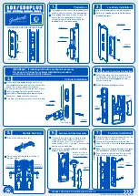
Inactive Case
1. Remove cover from inactive case chassis.
2. Mount chassis to door as indicated in Figure 10 and Figure 11.
Note
Active case is larger than inactive case.
Figure 12
Wood: #10 x 1-1/4"
Phillips flat head
(Total = 4)
Metal: #10-24 x 3/4"
Phillips flat under cut
(Total = 4)
Inactive case mounting screws - Actual size
Inactive case mounting screws - Actual size
e
Outside Trim
1. Thread cylinder into outside trim (if applicable).
2. Slide through-bolt screws through inside chassis and door.
3. Align outside trim with exposed through-bolt screws and secure.
1/4 -20 x 2-3/8"
Phillips Flat Head
(Total = 2)
Outside trim mounting screws - Actual size
Figure 14
#10-24 x 2"
Phillips Oval Head
Machine Screw
(Total = 2)
Cylinder mounting screws - Actual size
Figure 10
Inactive case
side (near
door hinge)
Hinge
side
Figure 11
Figure 13
Outside trim
Chassis
Door


