


ARKEL Elektrik Elektronik Ltd.
Ş
ti. www.arkel.com.tr
08.2012
ADrive
27
13.2.3. Incremental encoder connection for asynchronous motors
Incremental encoder connection for closed loop asynchronous drive is made to the terminals on
the ADrive.
Encoder connection terminals:
Encoder –A
Encoder phase A inverse
A
Encoder A
Encoder phase A
Encoder –B
Encoder phase B inverse
B
Encoder B
Encoder phase B
JP
Jumper (+7.5V) The unused encoder phase terminals (A inverse and B inverse)
must bridged to this terminal (for HTL Encoder)
+15V
+15V Supply
Supply voltage for HTL Encoder (Imax: 200 mA)
+5V
+5V Supply
Supply voltage for TTL Encoder (Imax: 400 mA)
0V 0V
Supply
ground
Before connecting the encoder, observe encoder operating voltage and switch off the
inverter.
Use a shielded cable for connection. Do not ground the encoder through both the motor
and inverter. If the encoder is isolated from the motor
,
and from ground, then connect the
cable shield to the inverter housing.
Motor cable and encoder cable channels should be separate. Minimum distance between
cables should be at least 10cm.
To minimize the distortion, cable lengths should be as short as possible.
13.2.3.1.
Incremental encoder simulation outputs:
If the lift controller needs the incremental encoder for shaft copying then use the simulation outputs
on ADrive.
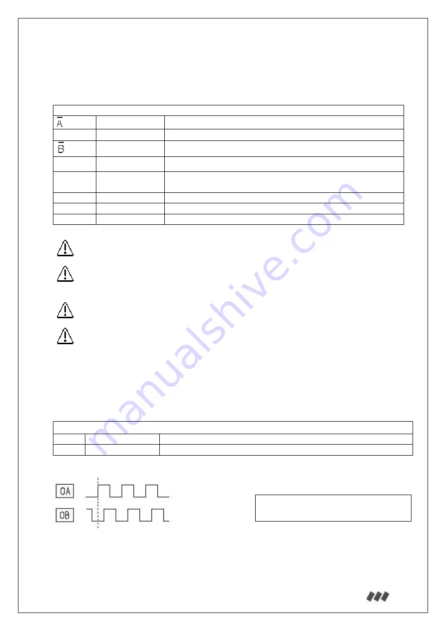
Incremental encoder simulation outputs:
OA
Encoder A
Encoder phase A
OB
Encoder B
Encoder phase B
The resolution of the encoder simulation outputs is identical with the encoder resolution.
See the circuit diagram of ADrive simulation outputs for connection.
Output signal high: Max. 14V/10mA
Output signal low: Min. 1V/10mA
ADrive