3-31
3
CC829B
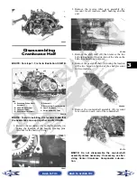
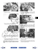
7. Remove the one-way clutch (D) from the clutch
housing. Note the location of the green dot (or the
word OUTSIDE) for installing purposes.
8. Using a hydraulic press, remove the clutch hous-
ing assembly from the clutch cover. Account for
the left fixed drive spacer and an O-ring inside the
fixed drive spacer.
CF085
CC596
NOTE: Account for and inspect the clutch hous-
ing seal.
CF088A
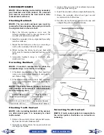
9. Remove the two Allen-head screws securing the
gear shift position switch; then remove the sensor.
Account for two neutral contact pins and two
springs.
CD997
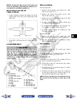
10. Remove the nut (left-hand threads) securing the
clutch shoe assembly (C).
FI279A
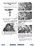
11. Remove the cap screw securing the oil pump drive
gear (B). Account for a cap screw, washer, pin, and
spacer.
KEY
A. Oil Pump Driven Gear
B. Oil Pump Drive Gear
C. Clutch Shoe Assembly
D. One-Way Clutch
(Green Dot MUST Show)
E. Final Drive Carrier Bearing
Housing
Back to TOC
Back to Section TOC
Next
Back


