3-30
CD963
CD966A
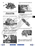
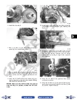
3. Remove the nut securing the fixed driven assem-
bly; then remove the assembly.
PR388
4. Remove the fixed drive face and V-belt.
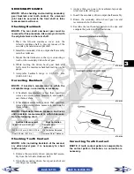
5. Using an impact driver, remove the cap screws
securing the air intake plate; then remove the plate
cushion.
PR393
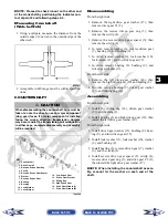
6. Remove the cap screws securing the clutch cover.
Note the location of the different-lengthed cap
screws for installing purposes. Using a rubber mal-
let, carefully remove the cover. Account for two
alignment pins.
CD973A
CD974A
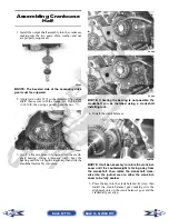
NOTE: For steps 7-13, refer to illustration
CC829B.
NOTE: To aid in installing, it is recommended that
the assemblies are kept together and IN ORDER.
! CAUTION
Care must be taken when removing the cover so the
cover gasket is not damaged.
Back to TOC
Back to Section TOC
Next
Back


