


2-11
2
TIRE INFLATION PRESSURE
Front and rear tire inflation pressure should be 0.70
kg-cm² (10 psi).
A low-pressure gauge is provided in the tool kit to
measure the air pressure in the tires. Check the air
pressure in all tires before each use of the vehicle.
Steering Components
The following steering components should be
inspected periodically to ensure safe and proper opera-
tion.
A. Steering wheel secure.
B. Steering has equal and complete full-left and
full-right capability.
C. Steering sector mounting bolts tight.
D. Ball joints not worn, cracked, or damaged.
E. Tie rods not bent or cracked.
F. Knuckles not worn, cracked, or damaged.
G. Cotter pins not damaged or missing.
H. Steering wheel tilt locks securely (XTX).
Driveshaft/Coupling
The following drive system components should be
inspected periodically to ensure proper operation.
A. Spline lateral movement (slop).
B. Coupling cracked, damaged, or worn.
C. Universal joints worn or missing bearings.
Suspension/Shock
Absorbers/Bushings
The following suspension system components should
be inspected periodically to ensure proper operation.
A. Shock absorber rods bent, pitted, or damaged.
B. Rubber damper cracked, broken, or missing.
C. Shock absorber body damaged, punctured, or
leaking.
D. Shock absorber eyelets broken, bent, or
cracked.
E. Shock absorber eyelet bushings worn, deterio-
rated, cracked, or missing.
F. Shock absorber spring broken or sagging.
G. Sway bar mountings tight and bushings secure.
Nuts/Bolts/Cap Screws
Tighten all nuts, bolts, and cap screws. Make sure riv-
ets holding components together are tight. Replace all
loose rivets. Care must be taken that all calibrated
nuts, bolts, and cap screws are tightened to specifica-
tions.
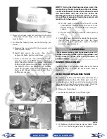
Ignition Timing
The ignition timing cannot be adjusted; however, veri-
fying ignition timing can aid in troubleshooting other
components. To verify ignition timing, use the follow-
ing procedure.
NOTE: To check ignition timing, the seats and
center console must be removed.
1. Attach the Timing Light to the spark plug high ten-
sion lead; then remove the timing inspection plug
from the left-side crankcase cover.
2. Start the engine and using the RPM function on
the speedometer/tachometer (XT/XTX) or using a
suitable tachometer (Prowler), run at 1500 RPM;
ignition timing should be 10° BTDC.
3. Install the timing inspection plug.
If ignition timing cannot be verified, the rotor may be
damaged, the key may be sheared, the trigger coil
bracket may be bent or damaged, or the CDI unit/ECU
may be faulty.
Back to TOC
Back to Section TOC
Next
Back


