5-8
CD071
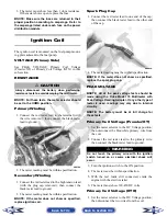
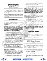
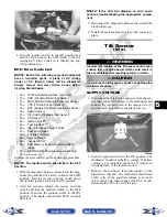
Ignition Switch
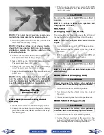
To access the ignition switch, dash switches, front
accessory connectors, and front switched accessory
connector, the dash must be unfastened and slid to the
rear.
VOLTAGE
1. Set the meter selector to the DC Voltage position.
2. Connect the red meter lead to the red wire; then
connect the black meter lead to ground.
3. Meter must show battery voltage.
NOTE: If the meter shows no battery voltage,
troubleshoot the main 30 amp fuse, the battery, or
the main wiring harness.
4. Connect the red meter lead to the red/black wire;
then with the black lead grounded, turn the igni-
tion switch to the ON position. The meter must
show battery voltage.
5. Connect the red meter lead to the yellow/green
wire; then with the black lead grounded, turn the
ignition switch to the START position. The starter
should engage and the meter must show battery
voltage.
NOTE: When the starter is engaged, battery volt-
age will be approximately 10.5 DC volts.
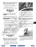
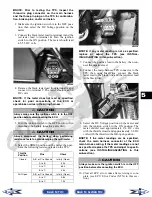
Headlight Switch
VOLTAGE
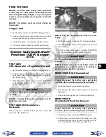
1. Connect the red meter lead to the gray wire; then
connect the black meter lead to the black wire.
2. Turn the ignition switch to the ON position. The
meter must show battery voltage.
NOTE: If the meter does not show battery volt-
age, troubleshoot the LIGHTS fuse on the power
distribution module, the ignition switch, or the
main harness.
3. Connect the red meter lead to the yellow wire;
then select the high beam position on the headlight
switch. The meter must show battery voltage.
4. Connect the red meter lead to either of the two
white wires; then select the low beam position on
the headlight switch. The meter must show battery
voltage.
NOTE: The battery voltage will show lower in
steps 3 and 4 due to electrical loading of the head-
lights.
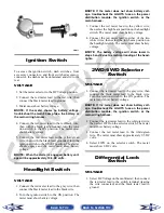
2WD/4WD Selector
Switch
VOLTAGE
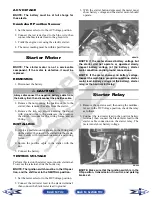
1. Connect the red meter lead to the gray wire; then
connect the black meter lead to the black wire.
Turn the ignition switch to the ON position. The
meter must show battery voltage.
NOTE: If the meter does not show battery volt-
age, troubleshoot the LIGHTS fuse on the power
distribution module, the ignition switch, or the
main wiring harness.
2. Connect the red meter lead to the white/red wire;
then select 2WD on the selector switch. The meter
must show battery voltage.
3. Connect the red meter lead to the white/green
wire. The meter must show approximately 9.5 DC
volts.
4. Select 4WD on the selector switch. The meter
must show 0 DC volts.
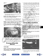
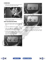
Differential Lock
Switch
VOLTAGE
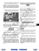
1. Select DC Voltage on the multimeter; then connect
the red tester lead to the switch terminal (leaving
the wire connected) and the black tester lead to
ground.
Back to TOC
Back to Section TOC
Next
Back

