5-13
5
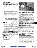
3. Depress the starter button while observing the
multimeter. The multimeter should drop to 0 volts
and a “click” should be heard from the relay.
NOTE: If a “click” is heard and any voltage is
indicated by the multimeter, replace the starter
relay. If no “click” is heard and the multimeter con-
tinues to indicate battery voltage, proceed to step
4.
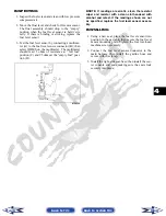
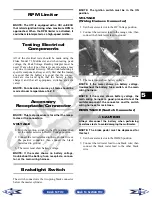
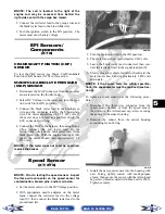
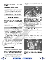
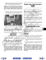
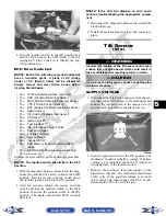
4. Disconnect the two-wire plug from the starter
relay; then connect the red tester lead to the green
wire and the black tester lead to the black wire.
PR297A
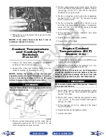
5. Depress the starter button and observe the multim-
eter.
NOTE: If battery voltage is indicated, replace the
starter relay. If no voltage is indicated, proceed to
Neutral Start Relay check.
CDI Unit
(Prowler/XT)
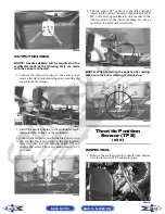
The CDI is located beneath the operator’s seat near the
battery.
NOTE: The CDI unit is not a serviceable compo-
nent. If the unit is defective, it must be replaced.
The CDI is rarely the cause for electrical problems;
however, if the CDI is suspected, substitute another
CDI unit to verify the suspected one is defective.
NOTE: Prior to replacing the CDI unit to assure
the CDI unit is defective, it is advisable to perform
a CDI peak voltage test (see Ignition Coil in this
section) and/or perform a continuity test of the wir-
ing harness from the CDI connector to the CDI
unit.
Electronic Control Unit
(ECU)
(XTX)
The ECU is located beneath the seat near the battery.
NOTE: The ECU is not a serviceable component.
If the unit is defective, it must be replaced.
The ECU is rarely the cause for electrical problems;
however, if the ECU is suspected, substitute another
ECU to verify the suspected one is defective.
This EFI system has a built-in feature that will only
allow an ECU of the same part number to be used in
this model. Do not attempt to substitute an ECU from
a different model as the system will not allow it to
start.
Error codes can be cleared by following the procedures
located in the ECU Error Codes (XTX) sub-section in
this section.
Regulator/Rectifier
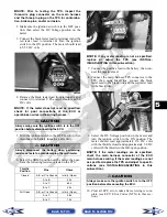
The regulator/rectifier is located under the operator’s
seat next to the battery. Try to verify all other charging
system components before the regulator/rectifier is
replaced.
TESTING
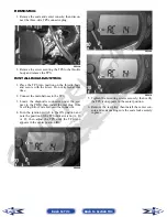
1. Start engine and warm up to normal operating
temperatures; then connect a multimeter (set at the
DC Voltage position) to the battery as follows.
2. Connect the red tester lead to the positive battery
post and the black tester lead to the negative bat-
tery post.
3. Slowly increase RPM. The voltage should increase
with the engine RPM to a maximum of 15.5 DC
volts.
NOTE: If voltage rises above 15.5 DC volts, the
regulator is faulty or a battery connection is loose
or corroded. Clean and tighten battery connec-
tions or replace the regulator/rectifier. If voltage
does not rise, check Voltage in this section. If
charging coil voltage is normal, replace the regula-
tor/rectifier.
Back to TOC
Back to Section TOC
Next
Back

