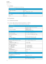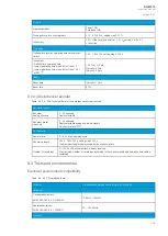
Current inputs
Phase current inputs: I
L1
(A), I
L2
(B), I
L3
(C)
Residual current channel I
01
(Coarse) (optional)
Residual current channel I
02
(Fine) (optional)
Current input magnitudes
RMS phase currents
RMS residual current (I
01
, I
02
) (optional)
Pick-up
Pick-up current settings:
- I
SET
high limit
- I
SET
low limit
- I
SUM
difference
- I
SET
ratio
- I2/I1 ratio
0.10…40.00 × I
N
, setting step 0.01 × I
N
0.10…40.00 × I
N
, setting step 0.01 × I
N
0.10…40.00 × I
N
, setting step 0.01 × I
N
0.01…100.00 %, setting step 0.01 %
0.01…100.00 %, setting step 0.01 %
Inaccuracy:
- Starting IL1, IL2, IL3
- Starting I2/I1
- Starting I01 (1 A)
- Starting I02 (0.2 A)
±0.5 %I
SET
or ±15 mA (0.10…4.0 × I
SET
)
±1.0 %I2
SET
/ I1
SET
or ±100 mA (0.10…4.0 × I
N
)
±0.5 %I0
SET
or ±3 mA (0.005…10.0 × I
SET
)
±1.5 %I0
SET
or ±1.0 mA (0.005…25.0 × I
SET
)
Time delay for alarm
Definite time function operating time setting
0.00…1800.00 s, setting step 0.005 s
Inaccuracy_
- Definite time (I
M
/I
SET
ratio > 1.05)
±2.0 % or ±80 ms
Instant operation time (alarm):
- I
M
/I
SET
ratio > 1.05
<80 ms (<50 ms in differential protection relays)
Reset
Reset ratio
97/103 % of the pick-up current setting
Instant reset time and start-up reset
<80 ms (<50 ms in differential protection relays)
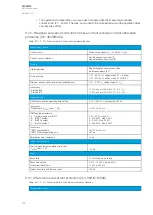
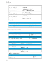
9.2.3.2 Circuit breaker wear monitoring
Table. 9.2.3.2 - 224. Technical data for the circuit breaker wear monitoring function.
Pick-up
Breaker characteristics settings:
- Nominal breaking current
- Maximum breaking current
- Operations with nominal current
- Operations with maximum breaking current
0.00…100.00 kA, setting step 0.001 kA
0.00…100.00 kA, setting step 0.001 kA
0…200 000 operations, setting step 1 operation
0…200 000 operations, setting step 1 operation
Pick-up setting for Alarm 1 and Alarm 2
0…200 000 operations, setting step 1 operation
Inaccuracy
Inaccuracy for current/operations counter:
- Current measurement element
- Operation counter
0.1× I
N
> I < 2 × I
N
±0.2 % of the measured current, rest 0.5 %
±0.5 % of operations deducted
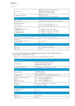
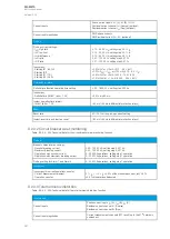
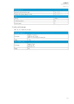
9.2.3.3 Total harmonic distortion
Table. 9.2.3.3 - 225. Technical data for the total harmonic distortion function.
Input signals
Current inputs
Phase current inputs: I
L1
(A), I
L2
(B), I
L3
(C)
Residual current channel I
01
(Coarse)
Residual current channel I
02
(Fine)
Current input magnitudes
Current measurement channels (FFT result) up to the 31
st
harmonic
component.
A
AQ
Q-M210
-M210
Instruction manual
Version: 2.04
347


