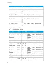
Figure. 7.4 - 178. Trip circuit supervision with one DI and one non-latched trip output.
Note that the digital input that monitors the circuit is normally closed, and the same applies to the alarm
relay if one is used. For monitoring and especially trip circuit supervision purposes it is recommended
to use a normally closed contact to confirm the wiring's condition. An active digital input generates a
less than 2 mA current to the circuit, which is usually small enough not to make the breaker's open coil
operate.
When the trip relay is controlled and the circuit breaker is opening, the digital input is shorted by the
trip contact as long as the breaker opens. Normally, this takes about 100 ms if the relay is non-latched.
A one second activation delay should, therefore, be added to the digital input. An activation delay that
is slightly longer than the circuit breaker's operations time should be enough. When circuit breaker
failure protection (CBFP) is used, adding its operation time to the digital input activation time is useful.
The whole digital input activation time is, therefore, t
DI
= t
CB
+ t
IEDrelease
+ t
CBFP
.
The image below presents the necessary settings when using a digital input for trip circuit supervision.
The input's polarity must be NC (normally closed) and a one second delay is needed to avoid nuisance
alarm while the circuit breaker is controlled open.
Figure. 7.4 - 179. Settings for a digital input used for trip circuit supervision.
Non-latched outputs are seen as hollow circles in the output matrix, whereas latched contacts are
painted. See the image below of an output matrix where a non-latched trip contact is used to open the
circuit breaker.
A
AQ
Q-M210
-M210
Instruction manual
Version: 2.04
304


