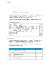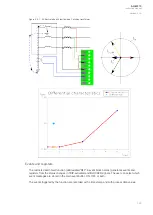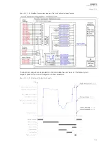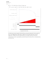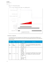
Picture 2 (bottom left). The LOGIC_OUT1 signal is connected to the I> blocking input (NOC1, first
stage overcurrent) function to block the stage in motor start-ups.
Picture 3 (right). The high overcurrent detection signal can also be directly connected to the output
relay. This way there is no need for extra logics for fault clearing control which makes fault clearing very
fast.
Alternatively, the user can release the tripping of the I> stage by letting the overcurrent function
operate on its set timer settings when a high overcurrent is detected. However, this requires that the
motor start detection current is set below the overcurrent stage.
Settings and signals
The settings of the motor status monitoring function are mostly shared with other motor protection
functions in the device's motor module. The following table shows these other functions that also use
these settings.
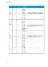
Table. 5.3.8 - 67. Settings of the motor status monitoring function and how they are shared by other protection functions.
Name
Range
Step
Default
Protection
functions
Description
Motor Start
0: DOL
1: Star-Delta
2: Soft start
-
0: DOL
- Motor status
monitoring
- Motor start
monitoring
(Ist>; 48)
The motor starting mode selection. The user can
select between Direct On Line (DOL), Star-Delta and
Soft start in future releases.
Motor In
Scaled
0.1...40.0xI
n
0.1xI
n
-
- Motor status
monitoring
- Machine
thermal
overload
protection
(Tm>; 49M)
- Motor start
monitoring
(Ist>; 48)
- Undercurrent
(I<; 37)
- Load jam
protection
(Im>; 51M)
The motor's nominal current scaled to per unit. If the
user selects
Object In in the CT settings, this value
should be 1.00. If scaled to the CT nominal, this value
may vary.
Motor In A
0.1...5000 A
0.1 A
-
- Motor status
monitoring
- Machine
thermal
overload
protection
(Tm>; 49M)
- Motor start
monitoring
(Ist>; 48)
- Undercurrent
(I<; 37)
- Load jam
protection
(Im>; 51M)
The motor's nominal current in amperes.
A
AQ
Q-M210
-M210
Instruction manual
Version: 2.04
127


