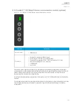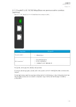
Connector
Description
X 4
Binary input 1 (+ pole)
X 5
Binary input 1 ( – pole)
The arc protection module is an add-on module with four (4) light sensor channels, two (2) high-speed
outputs and one (1) binary input. This module can be ordered directly to be installed into the device in
the factory, or it can be upgraded in the field after the device's original installation when required. If
even one of the sensor channels is connected incorrectly, the channel does not work. Each channel
can have up to three (3) light sensors serially connected to it. The user can choose how many of the
channels are in use.
The high-speed outputs (HSO1 and HSO2) operate only with a DC power supply. The battery's positive
terminal (+) must be wired according to the drawing. The NO side of the outputs 1 or 2 must be wired
through trip coil to the battery's negative terminal (–). The high-speed outputs can withstand voltages
up to 250 VDC. The operation time of the high-speed outputs is less than 1 ms. For further information
please refer to the chapter titled "Arc protection module" in the "Technical data" section of this manual.
The rated voltage of the binary input is 24 VDC. The threshold picks up at
≥
16 VDC. The binary input
can be used for external light information or for similar applications. It can also be used as a part of
various ARC schemes. Please note that the binary input's delay is 5…10ms.
NO
NOTE!
TE!
BI1, HSO1 and HSO2 are not visible in the
Binary inputs and Binary outputs menus
(
Control
→
Device I/O), they can only be programmed in the arc matrix menu
(
Protection
→
Arc protection
→
I/O
→
Direct output control and HSO control).
8.7 RTD input module (optional)
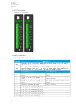
Figure. 8.7 - 191. RTD input module connectors.
A
AQ
Q-M210
-M210
Instruction manual
Version: 2.04
318


