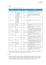
Name
Range
Step
Default
Description
Wf factor
for L/S T
const
0.0…1.0
0.1
0.5
The correction factor between the currently used long and short time
constants. With this setting the heating and cooling calculations can be
fine-tuned. A setting value of 0.5 means that 50 % of the heating or cooling
calculation is based on the long time constant and another 50 % is based
on the short time constant. A setting value of 0.0 means the calculation is
completely based on the short time constant, while a value of 1.0 means it
its completely based on the long time constant. This setting value is visible
when the time constants option "Multiple" is selected.
T const
dyn.
balancing
0: Fixed
1: Dynamic
-
0: Fixed
The selection of whether or not the thermal replica balances and switches
the time constants dynamically based on the detected motor status. The
switching is based on the settings given for maximum overload current and
for minimum locked rotor current. If "Dynamic" is selected, the thermal
replica switches the time constants. If "Fixed" is selected, no time constants
are switched. This setting value is visible when the time constants option
"Multiple" is selected.
Short
cool T
used
when
stop
0.0...3000min
0.1min 30.0min
The setting for how long the short cooling time constant is used when the
motor is stopped. The cooling is typically faster in right after the motor has
stopped. This setting may need adjusting depending on the application for
a perfect match. This setting value is visible when the time constansts
option "Multiple" is selected.
Short
cool T
used
when
stop (est)
0.0...3000min
0.1min 30.0min
The estimated setting for how long the short cooling time constant is used
when the motor is stopped. The cooling is typically faster right after the
motor has stopped. This setting value is visible when the time constansts
option "Multiple" is selected.
Cold
reset
default
theta
0.0…150.0%
0.1%
60.0%
The default theta when the function is restarted. It is also possible to fully
reset the thermal element.
This parameter can be used when testing the function to manually set the
current thermal cap to any value.
Table. 5.3.13 - 97. Environmental settings
Name
Range
Step Default
Description
Dev. temp
(tmax)
0: A
1: B
2: F
3: H
4: Manual
set
-
2: F
The maximum allowed temperature for the protected object. The default
setting is "F" which is +155 °C.
Obj. max.
temp
(tmax =
100 %)
0…500 deg
1
deg
125
deg
Visible when the Dev. temp. (tmax) is set to "4: Manual set".
Ambient
temp. sel.
0: Manual
set
1: RTD
-
0:
Manual
set
The selection of whether the thermal image biasing uses a fixed or a measured
ambient temperature.
Man.
amb.
temp. set.
0…500 deg
1
deg
40 deg
The manual fixed ambient temperature setting for thermal image biasing.
Underground cables commonly use +15 °C. This setting is visible if "Ambient
temp. sel." is set to "Manual set".
RTD amb.
temp.
read.
0…500 deg
1
deg
40 deg
The RTD ambient temperature reading for the thermal image biasing. This
setting is visible if "Ambient temp. sel." is set to "RTD".
Ambient
lin. or
curve
0: Linear est.
1: Set curve
-
0:
Linear
est
The selection of how to correct the ambient temperature, either by internally
calculated compensation based on end temperatures or by a user-settable
curve. The default setting is "0: Linear est." which means the internally
calculated correction for ambient temperature.
A
AQ
Q-M210
-M210
Instruction manual
Version: 2.04
189


