background image

SH-7000-Chroma-EN-04/17 


31 

4. 

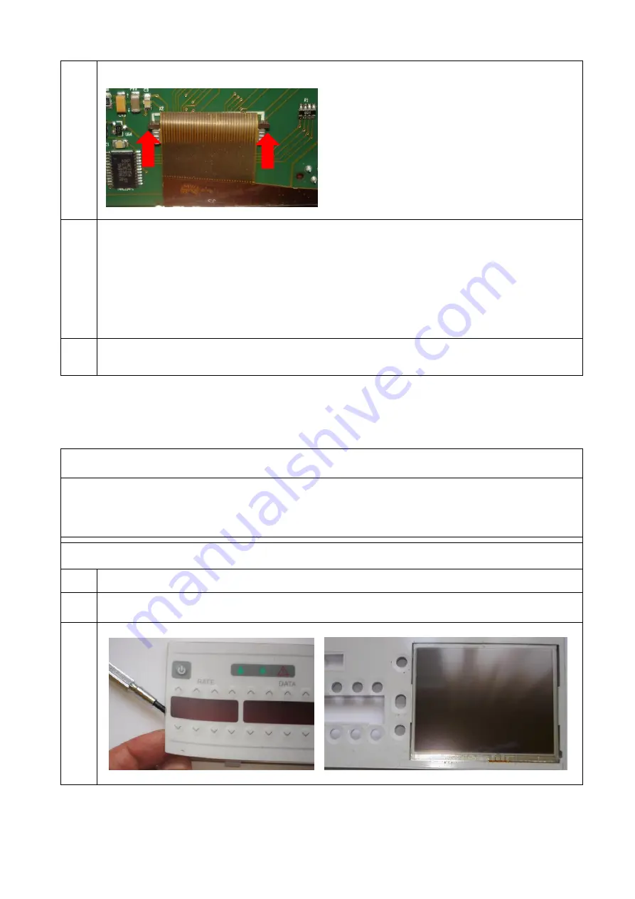
Carefully detach the Touch screen cable 


5. 

Connect the Touch screen cable on the new Display pcb 
Solder the AIL sensor cables 
Install the Display pcb 
Insert three screws 
Connect the Flat cable 
When reassembling the rear door cover, the order of the screws must be observed 
The shortest screw must be used at the indicated position 
Seal the new Door side sticker 

6. 

To update the Display pcb, follow the procedure described on 6.3 


5.12


 Replacement of the Touch Screen and Front Foil 

Tools & recommended spare parts:  

- Antistatic work place 

- Phillips screw driver No.1 
- LCD (73167) 
- Foil (76167) 


Procedure:


1. 

Dismantle door (5.9) 

2. 

Remove Display pcb (5.10) 

3. 

Remove Front foil.                               


Summary of Contents for Volumed nVP7000 Chroma

Page 1: ...Edition 4 17 ...

Page 2: ...SH 7000 Chroma EN 04 17 2 Displays and control elements 4 3 13 13 12 11 8 6 10 9 7 5 2 1 Volumed µVP7000 Chrom Front View Volumed µVP7000 Chroma Rear View ...

Page 3: ... 14 Tube guides 15 Stop flow mechanism here Robson clamp the other option is internal 16 Air in line detector 17 Pressure sensor 18 Peristaltic mechanism 19 Easy Clip empty bag detector Infusion set 20 Tubing 21 Drip chamber 22 Robson clamp Connectors and handling devices 23 Mains supply socket 24 Fuse 25 IR Interface 26 Nurse Call Connector 27 Connector for Easy Clip 28 Optional external Power Su...

Page 4: ...21 5 6 REPLACEMENT OF THE PERISTALTIC COVER 24 5 7 REPLACEMENT OF FRONT HOUSING AIR DETECTOR PLATE 25 5 8 REPLACEMENT OF UPSTREAM PRESSURE SENSOR 26 5 9 DISMANTLING THE DOOR 28 5 10 DOOR SCREWS DESCRIPTION 29 5 11 REPLACEMENT OF DISPLAY PCB 30 5 12 REPLACEMENT OF THE TOUCH SCREEN AND FRONT FOIL 31 5 13 REPLACEMENT OF THE DOOR AIR DETECTOR PLATE 32 5 14 ADDITIONAL OPTIONS AND AMENDMENTS 33 5 14 1 S...

Page 5: ...ry out repairs when device is powered off and disconnected from mains Take note of warning signs In addition to the switching power supply an internal battery enables the user to use the pump independently from mains supply The battery is a NiMH Battery 9 6V 2150 mAh Part No 71160 and is always being charged when the pump is plugged into mains The battery is charged on a cyclic basis which ensures...

Page 6: ...e required USB interface Part No 5316 and arcomed ag s own PremiumLink software are compatible with all common Window operating systems WARNING The Volumed µVP7000 Chroma is turned completely off during a software update to access the internal flash memories At this stage any false manipulation may cause pump failures It is of utmost importance that only trained personnel carry out updates because...

Page 7: ...on the corresponding address is shown The values can be changed with the arrow V Λ keys Figure Entering the password for Setup Mode 1111 Each parameter and its functionality are described in the chapters 3 3 and 3 4 2 2 Description of pump setup The database of the pump consists of approximately 55 addresses They consist of the following groups Address 0 19 Basic settings calibration apply globall...

Page 8: ...ntil step 3 is completed Step 3 enter the upgrade password supplied from Arcomed and confirm with select 0 4 7 Reserved 0 8 Door Lock Offset Not applied on 7000 1300 9 LCD Contrast allows adjusting the LCD contrast Not applied on Chroma 354 10 Speed correction see volume test 900 1100 11 Rate tuning allows to fine tune the speed depending on the rate Internal setting 0 12 Upstream pressure sensor ...

Page 9: ... beep 9 acoustic volume for alarms 3569 25 Preset Bolus rate in ml h internally limited to PVC 999 9 ml h Silicone 1200 ml h 1200 26 Max Bolus volume in ml The volume for an automatic bolus can t exceed this value 10 27 Max Rate in ml h Absolute max rate of the pump including rate during bolus applications Internally limited to PVC 999 9 ml h Silicone 1200 ml h 1200 28 KVO rate in 0 01 ml h max va...

Page 10: ...51 Production date year month 1606 52 Production number serial number 7000 98 Only PL 6 1004P and later versions IR data transfer Classic mode 0 Buffer mode 1 Only PL 6 1005 and later versions Buffer mode Enable PCA select excluding 30ml Plastipak NL 5 Buffer mode Enable PCS FIN 9 0 138 Total infused volume counter in ml Increasing counter 139 Total time in operation counter in seconds Increasing ...

Page 11: ... approved set Pressure gain address 15 adjustment required Adjust Pressure gain Pressure Transducer requires mechanical adjustment Adjust transducer Pressure Transducer damaged Replace transducer Low Occlusion Incorrect giving set Use Arcomed approved set Pressure gain address 15 adjustment required Adjust Pressure gain Worn door hinge Overhaul door Pressure Transducer requires mechanical adjustme...

Page 12: ...uent Air in Line alarm Ultrasonic faces of detector dirty or scratched Clean with soft tissue or cotton bud Faulty detector plates Replace detector Fluids containing excessive amounts of air Contact Arcomed representative AIL adapter not positioned properly Replace and realign AIL adapter Display cable defect Replace Display PCB Front PCB defect Replace front PCB Op amp on display PCB defect Repla...

Page 13: ...4 int or 114 Robson Pressure Transducer requires mechanical adjustment or is defect Adjust or replace pressure transducer Battery voltage too low Plug in mains Air in giving set Purge giving set LCD displays strange signs missing dot or lines blank LCD LCD glass broken defective cable to LCD Replace display PCB and LCD Language settings Check address 34 and or reload pump text IR interface not res...

Page 14: ...ng pressure during running Pressure sensor defective Replace pressure sensor Pump turns itself on and off when opening the door Display PCB defective Replace Display PCB or display cable LEDs show strange things Display PCB defective Replace Display PCB ...

Page 15: ...de In such cases the pump must not be used any more until the cause has been checked If the device cannot be repaired the pump should be sent to technical department or to arcomed ag 4 1 Meaning of error codes Code Meaning Cause Measure F 00 Communication error between processors Different Software on Display PCB and Main PCB Complete SW update Main PCB defect Replace Main PCB Display PCB defect R...

Page 16: ...n check If at start up Init Setup SW update restart if during operation and persistent check cable main PCB and display PCB replace if necessary F 12 13 Timing check Internal timing failed If persistent replace main or display PCB F 18 Clutch check 6000 Safety check clutch DC driver defect 6000 only If persistent Replace main PCB F 20 CRC Error SW problem Configuration Reload Configuration F 21 Re...

Page 17: ...any repairs on the device The acoustic sounder can exceed 100 dB when the housing is open Cover it or keep sufficient distance to your ears before switching on the device with an open housing 5 1 Replacement of Main PCB Tools recommended spare parts Antistatic work place 2 5 mm Hex driver Main pcb programmed VP7000 Chroma 76237 Procedure 1 Turn off pump unplug mains open housing using a 2 5 mm Hex...

Page 18: ... hole on the main board 7 Update the Main pcb following the instructions on chapter 6 4 5 2 Dismantling the Pump block Tools recommended spare parts Antistatic work place 2 5 mm Hex driver 5 5 mm socket wrench Philips screw driver No 1 Pump Block complete PVC 76695 Silicone 76685 Procedure 1 Turn off pump and dismantle main PCB 5 1 2 Remove Main PCB and store in antistatic environment Flat Cable f...

Page 19: ...e the four screws securing the door hinges 4 Loosen and remove the bolts and screws indicated 5 Unlatch the door The Pump block can be pulled out The Hall Sensor connector will unplug during removal During reassembly ensure this cable is connected ...

Page 20: ...e kit 76331 Procedure 1 Dismantle Main PCB 5 1 2 Dismantle Pump block 5 2 3 Removing the two back plate screws and carefully remove the back plate 4 Note the Springs type position and Brass spacer position and any washers under the springs 5 Reassemble pump in reverse order During reassembly do not apply much torque on the brass spacers holding the back plate to the pump block ...

Page 21: ...the Pump block 7 Adjust pressure sensor 7 1 8 Install Main pcb and battery Close the housing 5 5 Replacement of Stop Flow mechanism The Stop Flow mechanism opens and closes the tubing automatically to prevent free flow if the door is opened by accident Its function is self checked every time an infusion is started See also 5 11 1 for the additional stop flow counter plate Tools recommended spare p...

Page 22: ...daptor 5 Carefully remove the 2 5 mm Hex screw Loose the self tapping screw Kindly by hand lift the Front PCB slightly be careful not to damage the Hall sensor Note StopFlow tab under front PCB 6 Carefully remove the Stop flow Assembly 7 Loosen two fixing screws of the DC Motor 8 Mount DC Motor to new Stop Flow Housing Pull bottom of adaptor out to release bottom edge Pull adaptor down to release ...

Page 23: ...ab slide under it Attached the 2 5 mm Hex screw and tight Self Tapping screw 11 Hold the upper edge of the Stop Flow from rear firmly Slide top part up behind actuator first then push bottom edge back into front housing Install two screws fixing the adaptor to the StopFlow 12 Install the Pumping Block 13 Check calibration 14 Install Main pcb and battery Close the housing Correct Self Tapping Screw...

Page 24: ... damage of the cover Therefore it is necessary to replace the cover when worn Tools recommended spare parts Antistatic Work place 5 5 mm Hex driver 2 5 mm Hex driver Philips screw driver No 1 Peristaltic Cover part is included in several kits please check Part List manual Procedure 1 Dismantle Main PCB 5 1 2 Dismantle Pump block 5 2 3 Remove old cover the cover is secured with double sided tape on...

Page 25: ... Check calibration and install Main pcb and battery Close the housing 5 7 Replacement of Front Housing Air Detector Plate Tools recommended spare parts Antistatic Work place Philips screw driver No 1 5 5 mm Hex driver 2 5 mm Hex driver 2 mm Hex driver Air in Line Detector Kit 76046 Procedure 1 Dismantle Main PCB 5 1 2 Dismantle pump block 5 2 3 Dismantle Stop Flow Mechanism 5 5 ...

Page 26: ... plate before the red and black cable can be unsoldered Otherwise electric discharges of up to 400 V are created destroying the Display PCB 8 Solder new detector plate also short circuit 9 Reassemble pump in reverse order 5 8 Replacement of Upstream Pressure Sensor Tools recommended spare parts Antistatic work place 2 5 mm Hex driver 5 5 mm socket wrench Philips screw driver No 1 Pressure Sensor U...

Page 27: ...Remove adjustment and fixing screw 5 Remove old Pressure sensor and place new one 6 Connect pressure sensor cable built in pump block 7 Adjust Upstream sensor 7 2 and close the housing Front PCB Upstream sensor connector Pressure sensor connector Fixing screw Adjustment screw ...

Page 28: ... Labels 71231 Procedure 1 Remove the Main pcb 5 1 2 Unplug the display ribbon cable from Main pcb 3 Loosen the two screws indicated Carefully pull out the door as the photo shows Remove door from metal rod 4 Grip rubber seal and remove from housing Push out to the front now the door is free Pull the door cable out of housing 5 Remove the silver stickers do not remove the sticker of the Air In Line...

Page 29: ...left and right to the rod loose Tighten the screws after the door is locked in 5 10 Door screws description Tools recommended spare parts Antistatic work place Phillips screw driver No 1 Procedure 1 Several types of screw are used to attach the Door rear cover Pay attention at the description if you missed the position of the screws the Touch Screen will be damage and it will need replacement 2 Ei...

Page 30: ...t of Display pcb Tools recommended spare parts Antistatic work place Phillips screw driver No 1 Display pcb 75496 Procedure 1 Dismantle door 5 9 2 Detach Ribbon cable Remove three screws on display PCB Remove AIL cables 3 Lift off Display pcb from front housing ...

Page 31: ...e rear door cover the order of the screws must be observed The shortest screw must be used at the indicated position Seal the new Door side sticker 6 To update the Display pcb follow the procedure described on 6 3 5 12 Replacement of the Touch Screen and Front Foil Tools recommended spare parts Antistatic work place Phillips screw driver No 1 LCD 73167 Foil 76167 Procedure 1 Dismantle door 5 9 2 R...

Page 32: ...the rear door cover the order of the screws must be observed The shortest screw must be used at the indicated position Seal the new Door side sticker 5 13 Replacement of the Door Air Detector Plate Tools recommended spare parts Antistatic Work place Phillips screw driver No 1 Air in Line Detector Kit 76046 Solder station Procedure 1 Dismantling the door 5 9 2 Remove the two fixing screws of the ai...

Page 33: ...e do not forget to short circuit while soldering 7 Reassemble air detector plate in reverse order 5 14 Additional options and amendments 5 14 1 Stop flow counter plate New pumps are fitted with a counter plate to improve the strength of the shafts of the stop flow During disassembly and assembly the screw holding the counter plate the fixation to the main housing have to be removed and reassembled...

Page 34: ...omed ag s TecUpdate bulletin or can be requested at support arcomed com WARNING Due to the risk of failure during updates only trained and qualified personnel certification may carry out these procedures Any damage done onto the pump due to false handling do not fall under warranty terms There are different technical trainings for the use and handling of PremiumLink Do not use the following instru...

Page 35: ...ave to stand stable Do not interrupt data transfer during download Always press Download 1x in PremiumLink It is recommended to use a mouse 5 Press Download once in the download to pump section Pump will go into updating automatically First the LCD will blink after the buzzer will give clicking sounds Wait until the pump goes back into normal off mode 6 Turn pump on and off again 7 Un select Updat...

Page 36: ... on and off again 7 Click on Load set and select your set 8 Un select Update SW and Pump Text Select Drug Modes Configuration and Set Time in the download to pump section 9 Press Download once in the download to pump section Pump will go into updating automatically First the LCD will blink after the buzzer will give clicking sounds Wait until the pump goes back into normal off mode The Pump will e...

Page 37: ...at least 10mm Pump and IR interface have to stand stable Do not interrupt data transfer during download Always press Download 1x in PremiumLink It is recommended to use a mouse 5 Press Download once in the download to pump section Pump will go into updating automatically First the LCD will blink after the buzzer will give clicking sounds Wait until the pump goes back into normal off mode The Pump ...

Page 38: ...ur operation and safety tests 14 If it does success go to 21 If it doesn t success and the pump goes to defect some calibration data could be corrupted or lost Please go to 15 15 Turn ON the pump in Setup Mode 16 Select address 0 enter the value 9999 confirm with SELECT button 17 Select address 51 enter the production date of the device confirm with SELECT button 18 Select address 52 enter the ser...

Page 39: ...nd then by means of software The mechanical adjustment is necessary after replacement or if the software adjustment is not sufficient Used tools 2 5 mm Hex driver 0 89 mm Hex driver Infusion giving set filled with water Manometer with three ways tab A syringe filled with water must be connected to the manometer Procedure 1 Turn off pump and unplug open housing according to instructions for changin...

Page 40: ...ps to address 16 8 Check Stop flow position Stop flow must be open for the next calibration Insert new IV set filled with water and connected to manometer Adjust Pressure sensor mechanically with hex screw see section 3 until value in LED is minimum of 400 Note First time rather aim for 500 as the value tends to decrease after the testing Important Always tighten screw for final adjustment Press M...

Page 41: ...89 mm Hex driver Infusion giving set filled with water Procedure 1 Turn off pump and unplug mains Open housing according to instructions for changing the Main PCB 6 2 1 2 Access address 12 in the Service Mode Insert an IV line filled with water Close the door 3 Using the 0 89 Hex Driver loosen the adjustment screw a few turns 4 Using the adjustment screw set the value to 450 500 in the Volume ML w...

Page 42: ...brated in the so called volume test Process volume test 1 Insert IV Set in pump and switch on the pump 2 Fill a new administration set with water and connect to balanced scales Set Address 10 1000 Load administration set in pump Pre run set in pump Rate 400ml h Volume 10ml Start pump Test set in pump Rate 400ml h Volume 10ml Start pump Adjustment Read value on balance and compensate inverse with r...

Page 43: ... is however not mandatory to use all parts in the kits 8 1 Scope and Schedule of Safety Checks Schedule 24 months or 10 000 hours of operation Technical staff that have been trained and authorised in writing by arcomed ag or Arcomedical Infusion Ltd must check the unit according to the following list Visual check Check for Result Housing front foil Drop detector Door hinges Stop flow mechanism Cov...

Page 44: ... set to a mano meter Start pump in Setup Mode and go to Address 15 Built up pressure of 800 mbar externally Press and hold the START key Watch the manometer the pressure should not fall below 700 mbar at the beginning Keep pressing the START key and watch how the pressure rises PVC set maximum pressure pmax has to be within 1 5 bar and 2 5 bar Silicon Set maximum pressure pmax has to be within 1 2...

Page 45: ...ection for the nurse call plug ok 10 Battery test Charge the internal Accumulator completely Run the pump on battery The battery empty alarm must not come on within the first 3 hours ok 11 Electrical Safety Perform Electrical safety test according to EN 62353 ok Fuse ratings must correspond to the manufacturer s specification T500 mA 250V IEC127 III SEV 1064 Test results must be recorded in the Eq...

Page 46: ...hroma EN 04 17 46 9 Drawings and Layouts Note Arcomed AG delivers spare part kits rather than individual spare parts Contact Arcomed AG for the spare parts kits catalogue to determine what ordering number to use ...

Page 47: ...SH 7000 Chroma EN 04 17 47 ...

Page 48: ...SH 7000 Chroma EN 04 17 48 ...

Page 49: ...p Melody Sw update procedure Main and Display pcbs replacement procedure Calibration procedure Includes recommended spare parts on Repair chapter Chapter 8 Maintenance Version 0415 Added chapter 5 11 with stop flow counter plate Version 0315 SW 6 1000 Added configuration Addr 2 3 4 31 beep melody 56 57 note update kits 1 8 warning acoustic sounder 5 1 HW2 10 boc schematic Version 0514 Initial vers...

Reviews: