Anyload 805BS-B-17 Operation Manual Download Page 43


When the gross weight stored is something other than 0, use NFMT format. In


other cases, use GFMT format.


13.1 Print Format Commands 


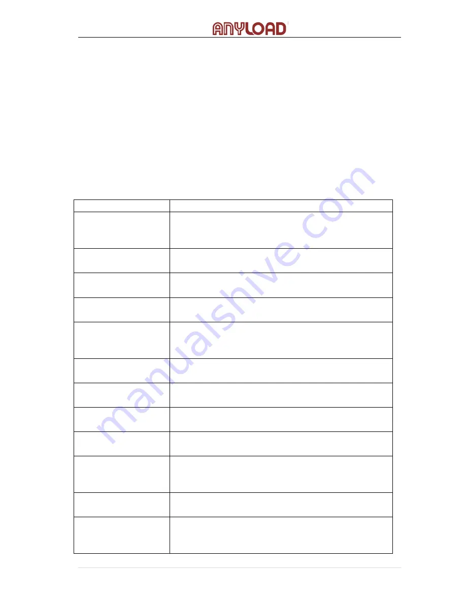
Print format commands are as shown in Table 13.1. Command included in the 

format strings must be enclosed between < > delimiters. Any characters outside 

of the delimiters are printed as text on the ticket.  Text characters can include 

any ASCII character shown in Appendices.  The maximum number of characters 

that can be input into each print format is 250. 
Table 13.1 Print Format Commands 

Command 

Description 

<G> 

Gross weight in displayed units.  The format is 

“XXXXXXX UU” where “XXXXXXX” is the weight and 

“UU” is the unit 

<N> 

Net weight in displayed units. Same format as in <G> 

command 

<T> 

Tare weight in displayed units. Same format as in <G> 

command. 

<CN> 

Consecutive number. The Format is “XXXXXX”. See 

Section 13.1. For print consecutive number setting. 

<CD> 

Count item code (must set count code first). The 

format is “XX”. See Section 7.3.6 for count item code 

setting. 

<CO> 

Count item quantity (must set count quantity first). 

The format is “XXXXX”. 

<D> 

Date of printing. Format: dd-mm-

yy, where dd is the 

day, mm is the month and yy is the year.


<I> 

Time of printing. Format: HH:MM:SS, where HH is 

the hour, MM is the minute and SS is the second. 


<P> 

Peak mode value (used only when Peak Mode is set). 

The format is “XXXXXXX” (including decimal point)   

<NL

nn

New line (nn is the number for CR and LF. Value 

must be in the range 1-

99. If nn is not specified, 1 is 

assumed).   

<SP

nn

Space (nn=number of space. Value must be in the 

range 1-

99. If nn is not specified, 1 is assumed).


<E> 

Command to complete print format setting. If a 

command is not ended wi

th  the  <E>  command, 

indicator is operated without print mode.  


42 

ANYLOAD 805TS & 805BS Series Weighing Indicator Operations Manual (v1703)


Summary of Contents for 805BS-B-17

Page 1: ...805TS 805BS Series General Purpose Digital Weight Indicators Operations Manual v1703 805TS B 17 805BS B 17 805BS TN B Lite Version ...

Page 2: ...e 11 7 2 4 Zero Scale 11 7 2 5 Print 11 7 3 Count Mode Operations 11 7 3 1 Gross Net Mode 12 7 3 2 Units 12 7 3 3 Zero Scale 12 7 3 4 Acquire Tare 12 7 3 5 Remove Stored Tare Value 12 7 3 6 Input Item Code 12 7 3 7 Printing in Count Mode 13 7 3 8 Fast Setup of Count Items Average Weight 13 8 Wire Installation 14 8 1 DC power supply 15 8 2 SW2 Switch 15 8 3 KOUT Relay signal outputs 15 8 4 SW3 Outp...

Page 3: ...int Consecutive Number 45 13 5 Date and Time Settings 46 14 Serial Communication 47 14 1 Continuous Transmission 47 14 2 Transmission Upon Request 48 14 2 1 Data Transmission Sequence 49 14 2 2 Communication Command 50 14 3 Serial Communication Test 51 15 Appendices 52 15 1Error Messages 52 15 2 Software Version and Default Configuration Parameters 53 15 2 1 Find out indicator software version 53 ...

Page 4: ...o zero tracking Unit exchange between kg lb Unit Selection kg lb g oz lb oz 0 8 in 20mm in height red LED display and with option for blue LED 143mm x 41mm LCD white background and blue font display and with option for blue background and white font Improper operation and fault indication Normal Weighing mode Peak mode and Count mode functions 2 way relay signal output not available in 805BS TN B ...

Page 5: ...edures described the work can only be performed by qualified technical personnel When using the equipment in surroundings with increased safety requirements the corresponding regulations must be observed The indicator may only be used with the power adapter supplied exclusively for use with the device Before inserting the power adapter the user must ensure that the operating voltage stated on the ...

Page 6: ...d by indicator light and different units can be toggled refer to Section7 1 2 Peak mode Indicator displays peak value of load acted upon the weighing instrument refer to Section 7 2 3 Count mode Indicator displays number of weighed items having the same weight refer to Section 7 3 Configurations Mode When SW2 switch is switched to on indicators are in the configurations mode Refer to Section 8 on ...

Page 7: ...5TS Fig 4 2 Front Panel Configuration for 805BS series Fig 4 1 and Fig 4 2 shows indicator display LED LCD indicator lights and keypad configuration Signs at the bottom of the keypad are for configuration operation use refer to Section 9 for details The signs are for inputting item codes in Count Mode refer to section 7 3 for details ...

Page 8: ... symbol is displayed when display showing units in oz N A lb oz The symbol is displayed when display showing units in lb oz Gross Light is on when display showing gross weight Gross The symbol is displayed when display showing gross weight Stable Light is on when load is stable or within the preset dynamic load range refer to F1 4 Menu for dynamic load setting Stable The symbol is displayed when l...

Page 9: ... is set not to Auto Zero Manual Zero If the load exceeds the zero scale setting in F1 3 Menu display shows actual load Refer to F1 3 Menu along with the F1 8 F1 9 Menu for further information 7 Operations The indicator goes to Weighing mode when the SW2 switch is turned off Under the Normal Weighing mode the Peak mode and Count mode can be set at F5 1 Configurations Menu refer to F5 1 Menu 7 1 Nor...

Page 10: ...eries or for the 805BS series Gross symbol is displayed remove the load from scale and wait until the Stable indication is present Press ZERO and the Zero light will turn on 805TS series or the Zero symbol will be displayed 805BS series This indicates that the Zero Scale setting is complete 7 1 4 Acquire Tare When no Tare is stored Tare light is off place the container on the scale and wait until ...

Page 11: ...TS button will display the available units like kg lb or oz Corresponding unit indicating the light is on for 805TS while indicating symbol is displayed for 805BS When Peak mode operation is activated Set light is on for 805TS and Set symbol is displayed for 805BS the UNITS button does not function to show available units 7 2 2 Peak Normal Weighing Mode When Set light is on 805TS or Set symbol is ...

Page 12: ...y 1 The Print format can be set at F8 Menu refer to Section 13 for Print Format To print Peak value ensure that it has been set up properly in the Print format settings 7 3 Count Mode Operations Only when F6 1 Menu is set to None mode F5 1 Menu can be set to Count mode If F5 1 2 the indicator will turn to Count Mode Count light is on for 805TS series or Count symbol is displayed for 805BS series T...

Page 13: ...ymbol is displayed 805BS series Press TARE and Tare value weight of container is stored The display will show the Net weight and the Net light 805TS series will be on or the Net symbol will be displayed 805BS series refer to F6 1 Menu Note Only when the tare value displayed is less than 6 digits the tare value can be successfully stored otherwise the tare option will not activate 7 3 5 Remove Stor...

Page 14: ...eight To obtain the average weight of a count item without going into the Configuration mode follow these procedures below 1 Enter the Input Item Code according in Section 7 3 6 Set the Item Code 00 Display shows P 00 2 Remove all weights from the scale Press to zero the scale Display shows CAL while calibration is in progress 3 After zeroing the scale display proceeds to Count Items Average Weigh...

Page 15: ...es Note When connect to 4 wire load cell please turn SW1 ON When connect to 6 wire load cell please turn SW1 OFF SW3 SW4 14 ANYLOAD 805TS 805BS Series Weighing Indicator Operations Manual v1703 sample quantity set in 3 above Press to calculate the average weight Press to cancel Count Items Average Weight Setup and return to the Weighing mode Display shows the count items average weight and returns...

Page 16: ...17 805BS B 17 8 4 SW3 Output RS485 COM SW3 switch is used to switch between output RS485 and COM mode When RS485 output mode is turned ON left the RS485 output mode is activated otherwise the COM output mode is activated Note Only 805TS B 17 805BS B 17 have this option not equipped in 805BS TN B 8 5 SW4 Output USB RS232 SW4 switch is used to switch between output USB and RS232 mode When USB output...

Page 17: ...able in 805BS TN B 8 8 Printers When hooking up a printer to the indicators 805TS 805BS series use connections 2GND 2RXD and 2TXD shown in Fig 8 1 To ensure the indicator is able to print on command set the serial mode F4 3 equal to comm 1 9 Configurations Configure the indicator in the following steps Remove the back panel of indicator Turn on the SW2 switch Indicator will now be in Configuration...

Page 18: ...alibration Calibrate indicator See Section 9 2 3 and Section 10 F4 Serial Configure serial communication ports See Section 9 2 4 and Section 14 F5 Mode Set weighing mode and unit weight of counted items See Section 7 Section 9 2 5 and Section 11 F6 Relay Set Relay operation modes See Section 9 2 6 and Section 12 F7 Ver Indicate software version and regenerate default configuration parameters See S...

Page 19: ...he default values for each indicator are Fig 9 1 3 Menu Configuration Flow Diagram There are 4 directional keys to be used for configuration operation are for horizontal movement in the same level menu and parameters are for moving up and down through different level menus is for confirming a choice of parameter in a menu 18 ANYLOAD 805TS 805BS Series Weighing Indicator Operations Manual v1703 Fig...

Page 20: ...fixed value use to move horizontally and use to store the selected parameter and to return to the last menu When a parameter value of a menu is editable as shown in Fig 9 1 4 directional keys are used to edit the digit selected and to increase or decrease the value of the selected digit Fig 9 1 4 Editable Parameter 19 ANYLOAD 805TS 805BS Series Weighing Indicator Operations Manual v1703 Use ...

Page 21: ...9 2 1 F1 Configuration Menu Fig 9 2 1 1 F1 Configuration Menu Structure 20 ANYLOAD 805TS 805BS Series Weighing Indicator Operations Manual v1703 ...

Page 22: ...1 3 Zero Range 0 1 9 FS Zero range Selects the range within which the scale can be zeroed The 1 9 selection is 1 9 around the calibrated zero point for a total range of 3 8 FS FS Grads D 1 100 FS F1 4 Motion Band 0 1D Motion band Sets the level in display divisions at which scale motion is detected If motion is not detected for 1 second or more the Stable light is on Some operations including Zero...

Page 23: ...ng rate of the indicator Power Up Auto Zero Specifies to automatically zero the scale when switching on the scale When selected 0 Yes indicator zeros the scale after finishing self checking Power Up Manual Zero Specifies to restore manually zero the scale when switching it on When 0 Yes is selected press zero button in the indicator to zero the scale and saves current zero for next powering up 1 2...

Page 24: ...ies 805BS series F2 1 Primary Unit 0 lb 0 P kg A lb Specifies the unit used of the Primary unit Note P stands as Primary Unit while A as Assistant Unit 1 kg 1 P kg A g N A 2 P kg A oz 3 P kg A lb oz 4 P lb A kg 5 P lb A g Backlight Time Off is applicable for 805BS B 17 only 23 ANYLOAD 805TS 805BS Series Weighing Indicator Operations Manual v1703 ...

Page 25: ... kg 17 P lb oz A lb 18 P lb oz A g 19 P lb oz A oz F2 2 Primary Unit Decimal Point 0 888888 Specifies the decimal position of the Primary unit Note If F2 4 5 and on during calibration in step F3 2 to edit the test weight value you can 1 88888 8 2 8888 88 3 888 888 4 88 8888 24 ANYLOAD 805TS 805BS Series Weighing Indicator Operations Manual v1703 ...

Page 26: ...the decimal position of the Assistant unit is defined by the decimal position of the Primary unit Only when F6 1 is set to 1 or 3 the decimal position of the Assistant unit could be set as F2 4 defined 1 88888 8 2 8888 88 3 888 888 4 88 8888 5 888880 F2 5 Assistant Unit Display Divisions 0 1 Specifies the displayed divisions of the Assistant unit 1 2 2 5 F2 6 Backlight Time Off for 805BS models No...

Page 27: ...his value after F3 3 WValue has been set Refer to Section 10 F3 2 WValue Display and edit the test weight value the value entered must above 100 Refer to Section 10 26 ANYLOAD 805TS 805BS Series Weighing Indicator Operations Manual v1703 Note 1 When selecting F6 1 0 NTEP or F6 1 2 Canada Assistant Unit Decimal Point Location and Assistant Unit Display Divisions will change automatically according ...

Page 28: ...r to Section 10 F3 4 REZero Press to remove an offset value from the zero and span calibration Use this parameter only after F3 1 WZero and F3 3 WSpan have been set Refer to Section 10 9 2 4 F4 Serial Interface Menu Fig 9 2 4 1 F4 Serial Menu 27 ANYLOAD 805TS 805BS Series Weighing Indicator Operations Manual v1703 F3 3 ...

Page 29: ...s for the number of data bits 1 7EVEN 2 7ODD F4 3 Mode 0 con Selects the mode of data transmission 0 con is for continuous transmission and 1 comm is for transmission upon receiving commands It must be set to 1 to use print function Refer to Section 14 1 comm F4 4 Address 0 Select address of serial port 1 2 3 4 5 6 7 8 9 28 ANYLOAD 805TS 805BS Series Weighing Indicator Operations Manual v1703 ...

Page 30: ...of three different operation modes If you want to select Peak and Counter Mode F6 1 must be set to 3 NONE otherwise Peak and Counter Mode won t be functional 1 Peak 2 Counter F5 2 Counted Item Code number Specifies the item code number of counted items Allowable numbers are 0 to 99 Refer to Section 11 for description of the setting of the counted item code 29 ANYLOAD 805TS 805BS Series Weighing In...

Page 31: ...F5 5 Average Weight Displays and edits the average weight of the counted items Refer to Section 11 9 2 6 F6 Relay Menu Fig 9 2 6 1 F6 Relay Menu Table 9 2 6 F6 Relay Menu F6 Relay Menu Parameter Choices Description Level 2 Submenu F6 1 mode 0 NTEP For OIML NTEP and CANADA application Tare removal is only allowed when Gross 0 When 1 OIML 2 CANADA 30 ANYLOAD 805TS 805BS Series Weighing Indicator Ope...

Page 32: ...r Specifies fixed value 1 Refer to Section 12 for Relay Output setup F6 3 P2 This function is not available in 805BS TN B Lite Version model Number Specifies fixed value 2 Refer to Section 12 for Relay Output setup F6 4 Password For 805TS B 17 805BS B 17 805BS TN B Number The password is required when entering or exiting configuration mode refer to Section 15 2 3 F6 5 User Overload For 805TS B 17 ...

Page 33: ...eration The initial value of this parameter is set to the start up value specified on the CONSTU F7 2 value Refer to Section 13 4 F7 2 CONSTU Number Consecutive Number Start Up Value Refer to Section 13 4 F7 3 Version Soft Version Displays the software version installed in the indicator This value cannot be altered F7 4 DATE Date Format setting for the date is DD MM YY F7 5 TIME Time Setting of ti...

Page 34: ...Format Menu is used for setting Print format of serial print output Refer to Section 13 10 Calibration The calibration of these indicators consists of the following calibration procedures o Zero calibration o Providing the test weight or known weight and its weight value o Span calibration 33 ANYLOAD 805TS 805BS Series Weighing Indicator Operations Manual v1703 F7 6 ...

Page 35: ...d already successfully done the Weight Calibration and recorded its A D Count in each procedure You may not required to load the actual test weights in the scale for the span calibration Weight Calibration Procedures Suggestion In conducting the Weight Calibration procedures it is recommended to record all the A D count values generated by the indicator and the test weight value from F3 1 F3 2 F3 ...

Page 36: ...unt This A D count usually a 6 digit count can be used if recalibrating the indicator using the Digit Calibration Method Do not adjust this value Press again to save the span calibration value and go to the next menu Display shows F 3 4 6 F3 4 Menu is used to remove a calibration offset when hooks or chains are used to hang the test weights When display shows F3 4 there are 2 options If no other a...

Page 37: ...t weight value Enter the test weight value based on your recorded calibration settings then press to save the value and go to the next menu Display shows F3 3 5 When display shows F3 3 press to show the A D count of the original or previous span calibration Modify and enter the A D count 6 digit value for your recorded span calibration When done press to save and to go to the next menu Display sho...

Page 38: ...he count items setup consists of the following procedures o Item code o Zero scale o Sample quantity o Confirming Count Items Average Weight 37 ANYLOAD 805TS 805BS Series Weighing Indicator Operations Manual v1703 re zero calibration When done press to save the value and to return to F4 Menu Display shows F4 7 Turn off the SW2 switch to exit from Calibration mode and enter into Weighing Mode 0 0 0...

Page 39: ...and edit the code number Press to save the code number and proceed to the next menu The display shows F5 3 4 Remove all the weight from the scale platform when display shows F5 3 Press to zero the scale Display shows CAL while processing the zeroing operation When completed display shows F5 4 5 Press when display shows F5 4 Display shows the sampling quantity of the count items Use keys to specify...

Page 40: ...ht settings you had been stored in the indicator The code 00 will return the indicator to Fast Setup of Count Items Average Weight refer to Section 7 3 8 Press UNITS in switching from Count Mode to Weighing Mode 12 Relay Output Setup There are two relay signal outputs in the Relay function When the weight value is smaller than the weight value setting in F6 2 the Relay output 1 is switched on or s...

Page 41: ...d return to F6 3 Menu Display shows F6 3 5 When display shows F6 3 press and display shows the value of Relay 2 setting Edit Relay value according to Fig 10 2 When completed press to store the value and return to F6 1 Menu Display shows F6 1 6 Turn off the SW2 switch to exit from Calibration mode and enter into Weighing Mode Fig 12 1 Relay Output Menu 40 ANYLOAD 805TS 805BS Series Weighing Indicat...

Page 42: ...te 1 Must ensure F6 3 P2 value F6 2 P1 value to give proper relay outputs Note 2 Weight value is in net weight and is according to the unit in F2 1 setting Refer to F2 Menu in Section 9 2 2 13 Print Format 2 print formats via the serial port output o Gross weight print format o Net weight print format After confirming print format GFMT and NMFT press ...

Page 43: ...secutive number The Format is XXXXXX See Section 13 1 For print consecutive number setting CD Count item code must set count code first The format is XX See Section 7 3 6 for count item code setting CO Count item quantity must set count quantity first The format is XXXXX D Date of printing Format dd mm yy where dd is the day mm is the month and yy is the year I Time of printing Format HH MM SS whe...

Page 44: ... for the default print format Table 13 2 Default Print Format Format Default Format String Sample Output GFMT G GROSS NL 1564 23 LB GROSS NFMT G GROSS NL T TARE NL N NET NL 4567 2 LB GROSS 23 5 LB TARE 4543 7 LB NET 13 2 GFMT and NFMT Print Format Input Setting of GFMT and NFMT is as follows Fig 13 2 1 Print Format Input Flow Diagram ...

Page 45: ... the characters as shown in Appendix 15 5 _ is shown for characters not available in Appendix 15 5 6 While editing use to move between characters To delete a character from the string press Once deleted the indicator will return to F8 1 7 When character editing is completed press to return to 4 above and to perform editing other characters When finish editing press to return to F8 1 and display sh...

Page 46: ... to F8 Menu Display shows F8 5 Turn off the SW2 switch to exit from Calibration mode and enter into Weighing Mode 13 4 Print Consecutive Number Set print consecutive number in Print mode F7 1 Menu CONSNU is the current consecutive number The consecutive number value is increased by 1 following each print operation When start up indicator F7 2 is assigned as the initial consecutive number F7 2 is u...

Page 47: ...eighing Mode 13 5 Date and Time Setting 1 Follow points 1 and 2 to enter into F7 Menu 2 When display shows F7 1 press until display shows F7 4 see Fig 13 4 Press to enter into Date setup mode and display shows DD MM YY date 3 When date setup is complete press to return to F7 5 Menu Display shows F7 5 4 When display shows F7 5 press and display shows time HH MM SS Follow Fig 4 2 to set the current ...

Page 48: ...s as follows Fig 14 1 Serial Communication Menu 14 1 Continuous Transmission 1 Turn on the SW2 switch to set indicator to the Configuration mode Display shows F1 2 Press until display shows F4 see Fig 8 1 Press to go to F4 Menu Display shows F4 1 3 When display shows F4 1 press until display shows F4 4 4 When display shows F4 4 press to show serial ...

Page 49: ...d stop are set at 1 These parameters are suitable for continuous transmission and transmission upon request modes Fig 14 1 Format of Continuous Transmission 14 2 Transmission Upon Request Specify F4 4 1 as Section 14 1 above After selecting the mode indicator transmits data upon request according to Fig 8 3 and Fig 8 4 When receiving a command the indicator sends OK after transmitting the requeste...

Page 50: ... Fig 14 2 1 Transmission Format from PC Example Set BLACK to G which is 47H in ASCII code Inspection and BCC calculation are as follow ASCII HEX BCC G 47H 47H ETX 03H 44H 30H 74H OR with 30H 49 ANYLOAD 805TS 805BS Series Weighing Indicator Operations Manual v1703 ...

Page 51: ... 2 2 1 Transmit Current Weight Value Command data from PC BLACK Format G ASCII 71 Response data from indicator BLACK Format see Fig 14 2 2 1 Fig 14 2 2 1 Respond to BLACK data after receiving G command 50 ANYLOAD 805TS 805BS Series Weighing Indicator Operations Manual v1703 ...

Page 52: ...Data received in gross weight 1072kg 14 2 2 2 Zero Scale PC command data BLACK format Z ASCII 90 Indicator receives correctly and responds data BLACK OK Example PC sends command to indicator to zero scale PC sends 01H 31H 02H 5AH 03H 79H Indicator responds 01H 31H 02H 4FH 4BH 03H 37H 51 ANYLOAD 805TS 805BS Series Weighing Indicator Operations Manual v1703 ...

Page 53: ...nt item average weight too small Check scale range or increase sampling weight according to Section 11 E 6 No average weight set for count items Refer to Section 11 to set average weight E 7 Load cell input signal 20mV Check load cell and connecting cables EL Load cell input signal 4mV Check load cell and connecting cables OF Load value F1 5 Set value Reduce load on scale 15 2 Software Version and...

Page 54: ...figuration Parameters 1 Turn on the SW2 switch to set indicator to the Configuration mode Display shows F1 2 Press until display shows F7 see Fig 15 2 1 Press to show F7 1 Press until display shows F7 6 3 When display shows F7 6 press Display shows a 4 digit code 0000 Edit it to 0711 according to Fig 10 2 Press 4 There are 2 possible outcomes If input code is correct display shows Set Then there a...

Page 55: ... password to be 11111 edit the F6 4 to P11111 then accept by pressing the tare key Switch back the SW2 jumper to DFT and check the display if the indicator is switched to weighing mode Once the indicator is in weighing mode switch back again the SW2 switch to CFG and check the indicator should still be in weighing mode The password is enabled Re install the back panel 4 To enter the Configuration ...

Page 56: ... the graduations should be 100 0 1 1000 For 0 01 division the graduation should be 10000 and so on 5 Enter the value of graduations in F1 1 submenu Refer to Section 9 2 for menu operation flow diagram Once F1 is displayed press Arrow down to enter F1 1 Press Arrow down again 00000 will display Press Arrow right or left to move to next digit and Arrow down or up to change values To enter value of 1...

Page 57: ...itial Signal 1 9mV Input Signal Sensitivity 0 2uV d minimum 1 5uV d recommended Zero Scale Range 1 9 FS 100 FS selectable Tare Range 0 100 FS Operating Temperature 10 C 40 C Operating Humidity 90 without dew Power Supply Adaptor Input 120VAC 60Hz 110mA Output 9VDC 600mA Input 120VAC 60HZ 110mA Output 12VDC 400mA Relay Outputs Up to 28VDC 2A up to 240VAC 1A Load Cell Bridge Voltage DC 5V can be con...

Page 58: ...57 ANYLOAD 805TS 805BS Series Weighing Indicator Operations Manual v1703 15 4 ASCII Codes Table ...

Page 59: ...15 5 Indicator Display Character 58 ANYLOAD 805TS 805BS Series Weighing Indicator Operations Manual v1703 ...

Page 60: ...Anyload Transducer Co Ltd Website www anyload com Email info anyload com Fax 1 866 612 9088 North America Toll Free 1 855 ANYLOAD 269 5623 ...

Reviews: