SECTION 5 – INSTALLATION INSTRUCTIONS
UL EX3470 ULC EX3470
PAGE 5-4 REV. 11 2014-SEP-01
R-102 Restaurant Fire Suppression Manual
INSTALLING THE DISTRIBUTION PIPING
Before the following procedures can be completed, the piping
design must already be determined; and the actuation and
expellant gas lines from the regulated release, each regulated
actuator, and each tank-enclosure or tank-bracket assembly
should already be installed.
These installation instructions are identical for single, double,
and multiple-tank systems except for the quantity of tanks and
hazard areas to be covered.
General Piping Requirements
1. Use Schedule 40 black iron, chrome-plated, or stainless
steel pipe and fittings.
NOTICE
Do not use hot-dipped galvanized iron
pipe or fittings in the agent distribution
piping.
2. Before assembling the pipe and fittings, make certain all
ends are carefully reamed and blown clear of chips and
scale. Inside of pipe and fittings must be free of oil and dirt.
3. The distribution piping and fitting connections, located in or
above the hood or the protected area, must be sealed with
pipe tape. When applying pipe tape, start at the second
male thread and wrap the tape (two turns maximum) clock-
wise around the threads, away from the pipe opening.
NOTICE
Do not allow tape to overlap the pipe
opening as the pipe and nozzles could
become plugged.
Thread sealant or compound must not be
used as it could plug the nozzles.
4. Distribution piping may be run independently or two agent
tanks may be manifolded together and run to the prede-
termined hazard area. Only agent tanks expelled from the
same cartridge may be manifolded.
NOTICE
Closely follow the piping requirements
for each size system, as detailed in the
“System Design” section, when installing
distribution piping.
5. Branchline tees can be used to create more than one
branch and can be installed as a thru tee, side outlet tee or
bull tee.
Pipe Hanger Recommended Guidelines
1. Space hangers as follows:
Maximum Recommended
Pipe Size
Distance Between Hangers
3/8 in.
5 ft (1.5 m)
2. Hangers should be placed between elbows when the
distance is greater than 2 ft (0.6 m).
Piping Installation
1. Starting at the tank, pipe directly from the union located on
the tank adaptor. A reducing fitting may be necessary to
conform to the distribution piping.
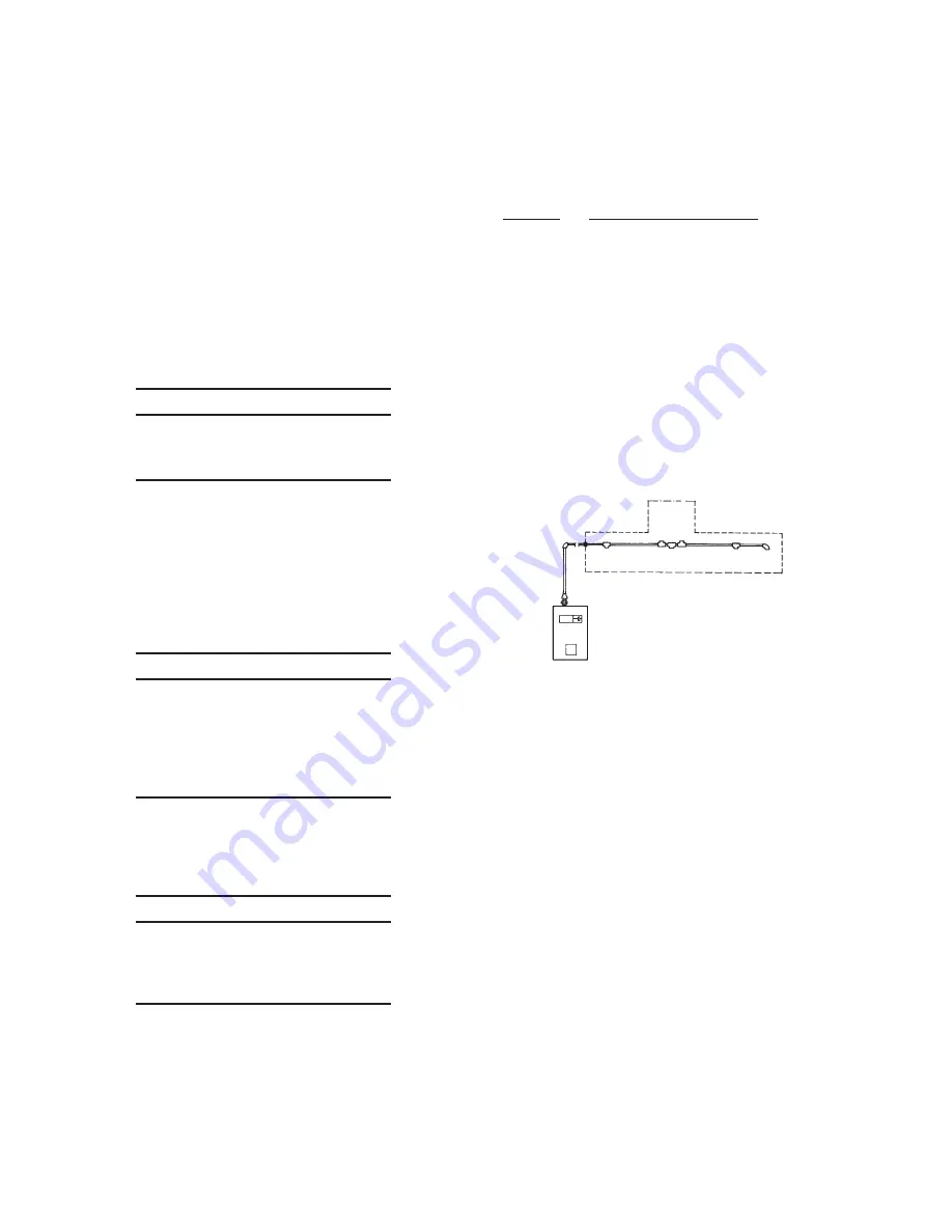
2. Based on the piping sketch developed in the “System
Design” section of this manual, install the supply line and
position the tees at points where branch lines must be
installed. See Figure 5-7.
3. Run all branch lines to the hazard area and connect each
nozzle. (Make certain all piping is securely bracketed.)
FIGURE 5-7
000302
4. Make certain all threaded connections are properly tight-
ened. Threaded connections located in the protected
area(s) and above the hood must be sealed with Teflon
pipe tape, as a minimum. Apply pipe tape to male threads
only. Make certain tape does not extend over the end of the
thread, as this could cause possible blockage of the agent
distribution.
Pipe tape minimizes friction between bearing surfaces of
the threads when threading pipe to fittings. The resulting
heat may expand the pipe threads before the joint is prop-
erly made. When the pipe threads cool and contract in
the fitting, the joint may become loosened causing cooking
grease to migrate into the distribution piping, and/or leakage
at the fitting during a pressure test or agent discharge.
Note: When required to provide pressure testing of pipe
or a system discharge test, it is recommended that all pipe
connections utilize Teflon pipe tape.
5. Install the correct nozzle(s) for each hazard area as previ-
ously designed. Some nozzles are required to be properly
oriented before they are positioned for aiming.
Summary of Contents for R-102
Page 2: ......


