Operator’s Manual
Rev 5/21/18
pg. 9
Instrument Installation and Setup
Site Requirements
To install and operate the
ANKOM
HCl
Hydrolysis System you will need the following:
•
Adjustable wrench
•
Tap water connection
•
Adequate power (see “Operating Environment” section)
Drying capability
It is extremely important that you completely dry your food or feed samples in an ANKOM
RD
Dryer or an oven
resistant to HCl fumes. If samples are not dried enough, residual water and acid left in the samples will lead to
inaccurate fat values. Overheating samples can lead to complexing of the fats resulting in lower values.
The ANKOM
RD
Dryer is specifically designed for hydrolysis samples and should be set at 110°C. This will result in
the appropriate temperature of 102°C inside the bag. If you are drying samples using a laboratory oven, it is
recommended that you use a mechanical convection oven set to 102°C±2°.
If you use a dryer, remember to regularly check the air flow through the
filter. For details, refer to the operator’s manual for your dryer.
Instrument Installation
The ANKOM
HCl
Hydrolysis System should be installed in a clean area free of dust and excessive moisture. The
instrument’s power cord must be plugged into a grounded receptacle. Ensure there are no kinks or bends in any of
the tubing that is connected to the instrument.
To install the ANKOM
HCl
Hydrolysis System, follow the procedure detailed below.
1.
Remove the instrument from the shipping container and set it on a smooth level surface near a drain and a
cold water supply.
WARNING:
Due to the corrosive nature of hydrochloric acid, it is
recommended that the instrument be operated in an acid ventilation hood
separate from other instruments that are subject to corrosion.
2.
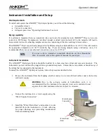
Connect the instrument to a water supply using the
“Water Supply Connection.”
3.
Install the “Water Drain Hose” and position it to run
downhill from the instrument to a drain, allowing
for proper drainage and preventing condensation
from accumulating inside.
Water Drain
Hose
Water Supply
Connection
Vent Hose
Summary of Contents for XT4
Page 2: ...This page intentionally left blank ...
Page 4: ...This page intentionally left blank ...
Page 12: ...Operator s Manual pg 12 Rev 5 21 18 This page intentionally left blank ...
Page 24: ...Operator s Manual pg 24 Rev 5 21 18 This page intentionally left blank ...
Page 25: ...Operator s Manual Rev 5 21 18 pg 25 Appendix A Electrical Diagram pg 1 of 3 ...
Page 26: ...Operator s Manual pg 26 Rev 5 21 18 Appendix A Electrical Diagram pg 2 of 3 ...
Page 27: ...Operator s Manual Rev 5 21 18 pg 27 Appendix A Electrical Diagram pg 3 of 3 ...


