Operator’s Manual
Rev 5/21/18
pg. 21
Periodic Maintenance
Cleaning the exterior of the instrument
At the end of each day use an ammonia-based cleaner (a mild base solution) and cloth to wipe the outside of the
instrument, making sure to clean the hinge on the Vessel Lid.
Do NOT use Acetone to clean the instrument.
Cleaning the interior of the Vessel
To restore the white color to the Vessel, periodically run a bleach solution through the instrument using the
procedure detailed below.
1.
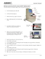
Turn the water supply on.
2.
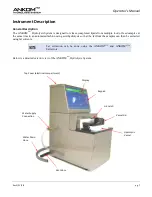
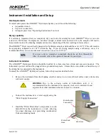
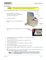
Pull the Lid Latch up to open the Vessel Lid.
3.
Pour 600 ml or enough of a bleach solution into the Hydrolysis Vessel to cover the two ports in the back
wall of the vessel.
4.
Push the Lid Latch down to close the Vessel Lid.
5.
Press ENTER on the Keypad.
6.
Use the UP/DOWN arrows on the Keypad to enter a hydrolysis time of 60 minutes.
7.
Press ENTER on the Keypad.
8.
Use the UP/DOWN arrows on the Keypad to enter a hydrolysis temperature of 90°C.
9.
Press ENTER on the Keypad.
10.
Use the UP/DOWN arrows on the Keypad to enter a rinse time of 20 minutes.
11.
Press ENTER on the Keypad.
12.
Make sure the Vessel Lid is closed (a message on the Display will remind you to do this).
13.
Press START on the Keypad. The bleach solution will automatically run through the instrument. When the
process has completed, the Display will show “Process Complete.”
Replacing the HCl Fuses
To replace the fuses in the ANKOM
HCl
Hydrolysis System, follow the procedure detailed below.
1.
Turn off the instrument power and unplug the Power Cord from the outlet.
2.
Remove the two screws on the Top Cover and set them aside.
3.
Swing the Top Cover down exposing the electrical compartment.
4.
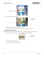
Locate the Fuse Holders on the terminal strip (see the image on the following page). There are two fuses
within the instrument; one for each pole (100 – 120V 10A or 220 – 240V 5A).
Summary of Contents for XT4
Page 2: ...This page intentionally left blank ...
Page 4: ...This page intentionally left blank ...
Page 12: ...Operator s Manual pg 12 Rev 5 21 18 This page intentionally left blank ...
Page 24: ...Operator s Manual pg 24 Rev 5 21 18 This page intentionally left blank ...
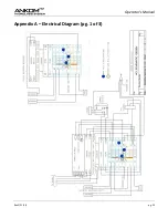
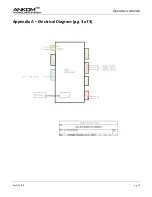
Page 25: ...Operator s Manual Rev 5 21 18 pg 25 Appendix A Electrical Diagram pg 1 of 3 ...
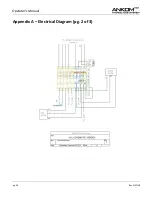
Page 26: ...Operator s Manual pg 26 Rev 5 21 18 Appendix A Electrical Diagram pg 2 of 3 ...
Page 27: ...Operator s Manual Rev 5 21 18 pg 27 Appendix A Electrical Diagram pg 3 of 3 ...

