


AMD5x Passive Infeed Unit and AMD5x Servo Drive - User Guide
ANCA MOTION
D-000129 Rev 09
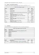
104
Disabling the PIU
9.4.5
In normal operation (no PIU faults), after the PIU has been Disabled the thyristors are turned off
(
Thyrist
=0) and the Regen Resistor will be turned ON (
Rgn
=1) for 3 seconds only to discharge the
DC Bus voltage. If the PIU is Enabled again during the 3s discharge period, then PIU normal starting
sequence will be delayed until the end of the 3s discharge period. If the DC Bus volts is greater than
50V after the 3s discharge period, then the fault bit
E_RsdlVolt
=1 will be set and the Regen Resistor
will continue to be turned on for up a further 6s in an attempt to discharge the DC Bus.
.
9.5
Monitoring the PIU
The EtherCAT interface to the PIU provides simple access to error status and analogue information, which can
assist system monitoring and fault finding. The start-up sequence shown in
Figure 9-2: Timing graph of typical
DC Bus voltage and status bits after enabling the PIU
can be replicated in normal operation by simply monitoring
appropriate variables.
DC Bus Measurements
9.5.1
The main function of the PIU is to generate DC Bus power, thus the DC Bus Voltage should be the
primary analogue measurement to be monitored during startup and load application.
The DC Bus Current & Power measurements show how much load is being supplied by the PIU.
These two measurements are filtered to remove mains ripple, and a negative value indicates power
is being dumped to the Regenerative Brake Resistor, while a positive value indicates power is being
supplied to the Drives.
Temperature Measurements
9.5.2
Heat generated by the PIU rectifier is removed by the heatsink which is cooled by air flow in the
external cooling duct. The heatsink temperature sensor is a slowly changing value dependant on PIU
load, cooling air temperature and flow rate. The sensor has a measuring range of 2°C to 120°C, with
trip point of 70°C where error
E_HeatsnkTemp
=1 is set. If this error occurs the user should check
cooling fans, load, and heatsink fins for contaminants such as dust.
The rectifier module temperature sensor is located internally to the rectifier. This sensor reads a
higher value than the heatsink temperature, and has faster response to load increases. The sensor
has a measuring range of 2°C to 120°C, with error trip point of 115°C where error
E_ThyristTemp
=1
is set.
The ambient temperature sensor is located on the controller PCB.
The wall and recessed PIU variants monitor the heatsink fan and will generate an EtherCAT warning
W_Fan
=1 if the fan is not connected, or Fan is not rotating correctly. This will not stop the PIU.
Control Supply Voltage
9.5.3
This is a measurement of customer 24 Vdc supply with a range of 0V to 48.18V. An error is
generated when the voltage is less than 19V and greater than 29V, and the error
E_24 V
=1 is set.
When the control voltage drops below 19V, the AMD5x Drive(s) will shut down.
Grid Frequency
9.5.4
Measurement of customer mains frequency begins after the PIU has been enabled. The calculated
measurement has an accuracy of 2% (±0.5Hz) and a measuring range of 47Hz to 64Hz. If the
measurement is out of range, the error
E_GridFrq
=1 is set. This error may occur after a mains
failure.
Summary of Contents for AMD5x Series
Page 12: ......


