Configuring Communication
68
10" Modero Touch Panels
Step 3: Configure an Ethernet Connection Type
Before beginning:
1.
Verify the panel has been configured to communicate either through an Ethernet cable (from the panel to
a valid Ethernet Hub) or to a wirelessly (from the panel to a compatible Wireless Access Point (WAP)).
2.
Verify that the NetLinx Master is receiving power and is communicating via an Ethernet connection with
the PC running NetLinx Studio.
3.
Connect the terminal end of the 12 VDC-compliant power supply cable to the power connector on the
rear/side of the touch panel.
4.
Verify the green Ethernet LED (from the rear Ethernet port on the Master) is illuminated (indicating a
proper connection).
5.
Verify the yellow LED (from the rear Ethernet port on the Master) is blinking (indicating
communication).
6.
After the panel powers-up, press and hold the grey Front Setup Access button (
for 3 seconds
) to proceed
to the Setup page.
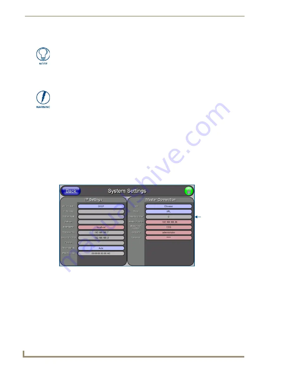
7.
Select
Protected Setup
>
System Settings
(located on the lower-left) to open the System Settings page
(FIG. 70).
When using Ethernet as your communication method, the NetLinx Master must first
be setup with either a Static IP or DHCP Address obtained from either NetLinx Studio
or your System Administrator.
Before commencing, verify you are using the latest NetLinx Master firmware.
FIG. 70
System Settings page
Obtained from
NetLinx Master
Summary of Contents for modero NXD-CV10
Page 1: ...Operation Reference Guide Touch Panels NXT D CV10 10 Modero Touch Panel Last Revised 7 2 2012 ...
Page 44: ...CV10 Touch Panel Accessories 32 10 Modero Touch Panels ...
Page 58: ...Installation 46 10 Modero Touch Panels ...
Page 88: ...Configuring Communication 76 10 Modero Touch Panels ...
Page 98: ...Upgrading Modero Firmware 86 10 Modero Touch Panels ...
Page 192: ...Appendix A 180 10 Modero Touch Panels ...
Page 206: ...Troubleshooting 194 10 Modero Touch Panels ...