


Configuring Communication
56
10" Modero Touch Panels
Step 5: Confirm and View the current AMX USB device connections
Use the CC-USB Type-A to Mini-B 5-wire programming cable (
FG10-5965
) to provide communication
between the mini-USB Program port on the touch panel and the PC. This method of communication is used to
transfer firmware KIT files and TPD4 touch panel files.
1.
Verify this direct USB connection (Type-A on the panel to mini-USB on the panel) is configured properly
using the steps outlined in the previous two sections.
2.
With the panel already configured for USB communication and the Virtual Master setup within NetLinx
Studio, its now time to verify the panel is ready to receive files.
3.
Click the
OnLine Tree
tab in the Workspace window to view the devices on the Virtual System.
The default System value is one
.
4.
Right-click on the System entry (
A
in FIG. 59) and select
Refresh System
. This causes a refresh of all
project systems, establishes a new connection to the Virtual Master, and populates the System list with
devices on your particular system.
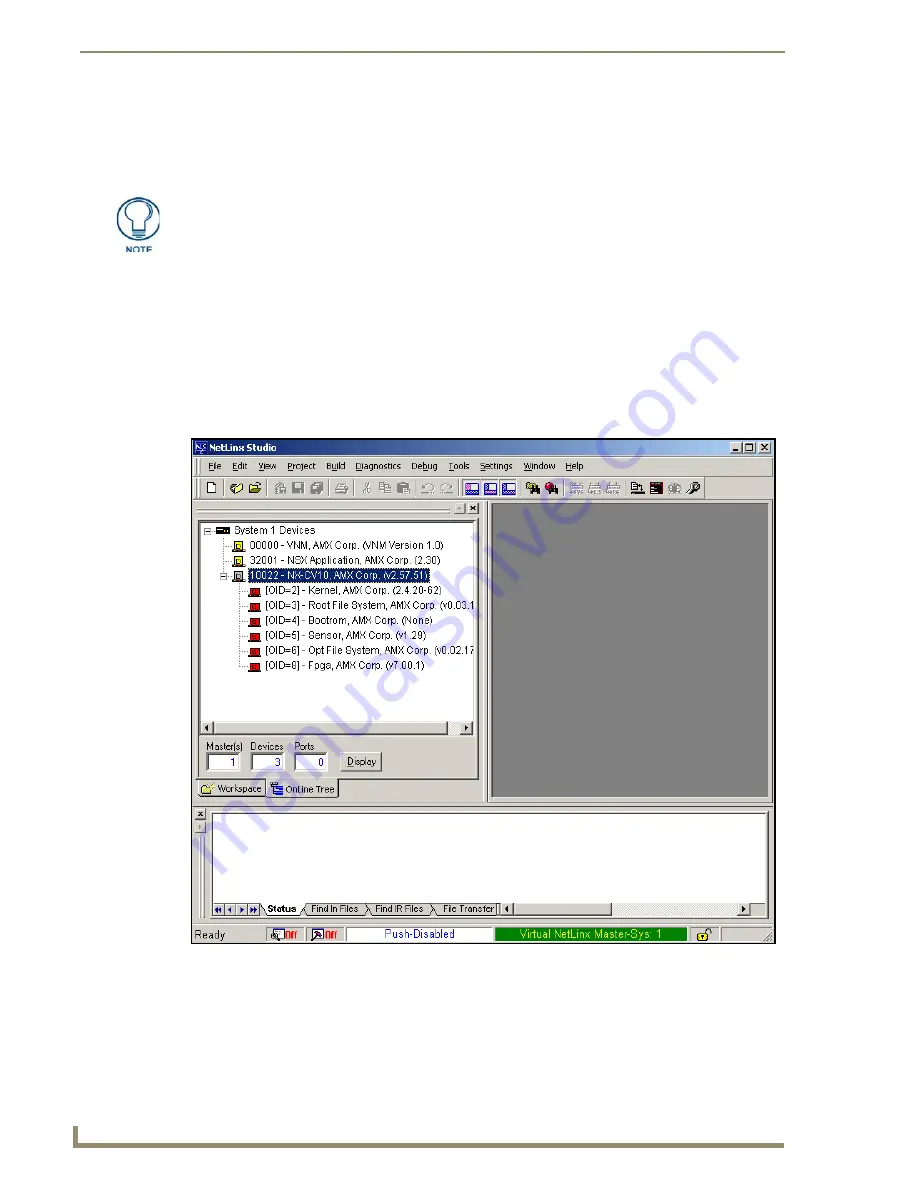
A mini-USB connection is only detected after it is installed onto an active panel.
Connection to a previously powered panel which then reboots, allows the PC to
detect the panel and assign an appropriate USB driver.
FIG. 59
Using USB for Virtual Master communication
Summary of Contents for modero NXD-CV10
Page 1: ...Operation Reference Guide Touch Panels NXT D CV10 10 Modero Touch Panel Last Revised 7 2 2012 ...
Page 44: ...CV10 Touch Panel Accessories 32 10 Modero Touch Panels ...
Page 58: ...Installation 46 10 Modero Touch Panels ...
Page 88: ...Configuring Communication 76 10 Modero Touch Panels ...
Page 98: ...Upgrading Modero Firmware 86 10 Modero Touch Panels ...
Page 192: ...Appendix A 180 10 Modero Touch Panels ...
Page 206: ...Troubleshooting 194 10 Modero Touch Panels ...


