background image

Configuration

17

 AVX-400 Enova Twisted Pair Presentation Switcher Operation/Reference Guide

Configuration

AMX DCS Software

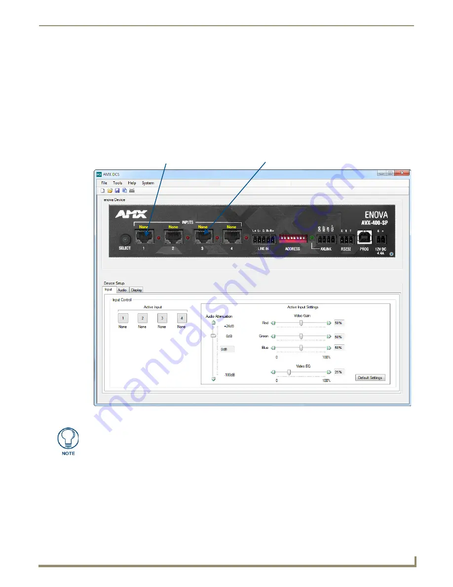
You can configure the AVX-400 and its functionality by using AMX DCS software (FIG. 27). The top of the window 
displays the device image of the front panel of the Enova AVX-400, and displays which inputs are valid by highlighting 
the source input. Clicking on a highlighted port on the device image changes the active input. (This does not work if you 
are working in Priority mode unless there are no active inputs on the AVX-400.) The active source input is indicated by 
the illuminated red LED beside the source input. 

FIG. 27  

AMX DCS main screen

Highlighted port indicates
valid wallplate connection and type

Non-highlighted port
indicates no wallplate connection

The DCS application is intended for configuration purposes and not for real-time use. 
In most cases, after configuring your system, you will not need to return to use the 
DCS application unless you have a configuration change to your system.

Summary of Contents for Enova AVX-400

Page 1: ...Operation Reference Guide Twisted Pair Presentation Switchers AVX 400 Twisted Pair Presentation Switcher Last Revised 9 12 2014...

Page 2: ...ked on the outside of each box The RMA is valid for a 30 day period After the 30 day period the RMA will be cancelled Any shipments received not consistent with the RMA or after the RMA is cancelled w...

Page 3: ......

Page 4: ......

Page 5: ...r 10 Preparing Captive Wires 11 Wiring a Power Connection 11 Installing a Suppression Ferrite 11 Rear Panel Components 12 DISPLAY CONTROL 12 SPEAKER 13 LINE OUT 13 Composite Output VIDEO 13 HD 15 Outp...

Page 6: ...ls 29 AxLink Levels 29 AxLink Commands 30 CI I O O 30 DOF 30 DON 30 DST 30 FILTER 30 GCT 31 INPUT 1 31 INPUTPROPERTY 1 31 LAMPTIME 31 PTOFF 31 PTON 31 PWR 31 RXOFF 32 RXON 32 SET BAUD 32 SSW 32 TEMP 3...

Page 7: ...itcher Operation Reference Guide MUT 36 PBD 36 PDI 36 PEN 36 PSS 37 PWR 37 RGN 37 SMD 37 SMT 37 SSW 37 TEMP 37 TON 38 TON 38 TON 38 TON 38 UMT 38 VEQ 38 VEQ 39 VGN 39 VID 39 VLA 39 VLA 39 VLA 39 VLB 4...

Page 8: ...iv AVX 400 Enova Twisted Pair Presentation Switcher Operation Reference Guide Table of Contents...

Page 9: ...ility Audio volume and tone control Built in audio amplifier The presentation switcher presents the respective output for the VGA RGB component and composite video sources All sources remain in their...

Page 10: ...nector that provides data to external control devices and allows the AVX 400 to be controlled from RS232 controller Configuration Port PROG 1 type B USB connector for configuring the switcher via DCS...

Page 11: ...UPX CS A EU Composite Universal Transmitter Wallplate EU FG1402 50 EW EB EA UPX RGB A DE RGB Universal Transmitter Decor Style Wallplate US FG1402 51 DW DB UPX RGB A UK RGB Universal Transmitter Wallp...

Page 12: ...Enova AVX 400 Twisted Pair Presentation Switcher 4 AVX 400 Enova Twisted Pair Presentation Switcher Operation Reference Guide...

Page 13: ...input turns on to show which source you have selected The select button does not function when you are working in Priority mode Source Inputs INPUTS 1 4 The Source inputs can accept video from devices...

Page 14: ...Pair RGB YPbPr CVBS S Video Color Pair 1 3 Red Y CVBS S1 Y 2 2 3 Red Y CVBS S1 Y 2 3 2 Blue Pr CVBS S3 C 3 4 1 Green Pb CVBS S2 1 5 1 Green Pb CVBS S2 1 6 2 Blue Pr CVBS S3 C 3 7 4 Audio Data Power Au...

Page 15: ...d connections FIG 8 You can connect a microphone to this input using a preamplifier Source and destination devices require either balanced differential or unbalanced single ended connections FIG 8 ill...

Page 16: ...shows the wiring diagram Always use a local power supply to power the Integrated Controller unit Make sure to connect only the GND wire on the AxLink PWR connector when using a separate 12 VDC power...

Page 17: ...RS 232 connect the wiring as shown in FIG 14 When using a Novara SP 08 AX 8 Button keypad connect the AVX 400 to the RS232 output port on the keypad Consult the documentation for the Novara SP 08 AX 8...

Page 18: ...pply must be connected to the corresponding locations within the power connector The current draw for the AVX 400 with no input plates is 750mA The following table lists the current draw for each type...

Page 19: ...onnector FIG 17 Follow these steps to wire a power connection 1 Insert the PWR and GND wires on the terminal end of the 2 pin 3 5 mm mini Phoenix cable Match the wiring locations of the on both the po...

Page 20: ...ols for data transmission This figure gives a visual representation of the wiring specifications for the DISPLAY CONTROL connector The table below provides information about the connector pins signal...

Page 21: ...ns FIG 23 illustrates options for wiring between output connectors and the destinations Composite Output VIDEO The composite output enables you to use a composite cable RCA Y to send video to a displa...

Page 22: ...output each for COMPONET and RGB VGA sources The following table lists the pinout configuration for HD 15 connector to RGB VGA connectors FIG 25 HD 15 Output connectors Video Output HD 15 Connector P...

Page 23: ...brackets from the optional mount kit FG525 to the sides of the switcher as shown in FIG 26 to mount the unit to any flat surface FIG 26 displays the mounting brackets set to attach to the underside o...

Page 24: ...Wiring and Device Connections 16 AVX 400 Enova Twisted Pair Presentation Switcher Operation Reference Guide...

Page 25: ...e image changes the active input This does not work if you are working in Priority mode unless there are no active inputs on the AVX 400 The active source input is indicated by the illuminated red LED...

Page 26: ...dows XP Service Pack 3 Professional French Windows 7 Home Premium 32 bit French Windows 7 Home Premium 32 bit Greek Windows XP Service Pack 3 Professional Spanish Windows 7 Home Premium 32 bit Italian...

Page 27: ...ect the manufacturer of the device you want to use Type Select the type of device you want to use Model Select the device model you want to use Variable Display Polling Rate Use the up and down arrow...

Page 28: ...tching 1 In the Device Setup area click the Display tab FIG 29 2 Click the Priority Switching option button in the Switching Mode section 3 Use the options menus in the Priority Switching area to indi...

Page 29: ...he changes to take effect Setting the Communication Speed The AVX 400 enables you to set the communication speed between DCS and the AVX 400 DCS sets the speed that is applicable for the firmware vers...

Page 30: ...Rate Data Bits Data Format Flow Control Parity and Stop Bits for the device You can change most of these options if necessary You cannot change any field that appears dimmed Cmd Data ASCII When you s...

Page 31: ...AVX only commands always begin with AVX_ If you remove this prefix from the command name AMX DCS will no longer view the command as AVX only AVX only command names have a limit of 10 characters Comma...

Page 32: ...From the File menu select Device Manager Library The Device Library Manager window opens 2 In the Device Selection area click the Import button 3 Navigate to a directory containing Novara plr prr or...

Page 33: ...e following options appear in this window Perform the following steps to use the ASCII to Hex tool 1 Enter text in the ASCII field 2 Click ASCII to Text The hexadecimal version of the text appears in...

Page 34: ...to transmit the command data to the device Any information returned from the device appears in the Feedback area To use this tool you must directly connect the SERIAL port on your PC to the device See...

Page 35: ...the latest firmware for the device Current Firmware Version Displays the current firmware version for the device This information is view only Device Model The device model of the unit you are updatin...

Page 36: ...r your device Make note of the location to which you save the firmware file When the download is complete return to the Enova Firmware update window 5 Click Select File navigate to the location the fi...

Page 37: ...9 to 255 are scaled to fit the audio level of 0 5 to 24dB The AxLink Levels for the AVX 400 are defined in the table below AxLink Channels Channel Description 24 Amplifier volume up when the channel i...

Page 38: ...DST A B C D E A power 0 unknown 1 on 2 off 3 warming 4 cooling B input 0 unknown 1 PC 2 component 3 composite 4 HDMI C lamp time 0 unknown D filter time 0 unknown E temperature 0 unknown One possible...

Page 39: ...returns the current input driving the output Syntax SEND_COMMAND INPUTPROPERTY 1 Sample Output Input PC Input Component Input Composite Input HDMI If the video input cannot be determined Input Unknown...

Page 40: ...ND dvRXRS232 RXON Sets the Rx serial port to transmit received characters to the Master SET BAUD Set the serial communication parameters Syntax SEND_COMMAND DEV SET BAUD baud parity data stop Variable...

Page 41: ...r On Serial Commands AMT Toggle amplifier mute Syntax AMT ASM Turns on the amplifier mute Syntax ASM ATA Sets the auxiliary input attenuation to the specified level Syntax ATA attenuation Variable att...

Page 42: ...lanced mute Syntax BMT 0D BSM Turns on the balanced mute Syntax BSM 0D BUM Turns off the balanced mute Syntax BUM 0D DCM Triggers a dynamic user command AMX advises you to place the AVX in passthru mo...

Page 43: ...or above 115200 FLT Queries the filter volume status of the display returns the current filter or volume status Syntax FLT 0D Sample Output Filter xxxx where xxxx filter If the system filter volume c...

Page 44: ...ned Lamp Unknown MMD Sets mono mode In mono mode the left and right inputs are mixed together and presented on both left and right output channels Syntax MMD 0D MUT Toggles the audio video mute Note T...

Page 45: ...assthru wallplates Syntax RGN input gain Variable input source input 1 4 gain the red gain level setting between 0 and 100 Note The number you enter for the gain setting should correspond to a percent...

Page 46: ...1KHz 5 2 5 KHz 6 5KHz 7 10KHz Example TON3 0D Increases the 500Hz tone band by 0 5dB TON Decrease the tone band by 0 5dB Syntax TON band Variable band tone band 1 7 1 100Hz 2 250Hz 3 500Hz 4 1KHz 5 2...

Page 47: ...1 110 B1 110 R2 110 G2 110 B2 110 R3 140 G3 140 B3 140 Note The number for the gain setting corresponds to a percentage between 0 and 100 For example a gain setting of 110 corresponds to a percentage...

Page 48: ...reaches its minimum level the AVX 400 responds with MIN Syntax VLB 0D VMT Toggle video mute Syntax VMT 0D VOL Sets amp and balance out volume to the same setting Syntax VOL volume Variable volume the...

Page 49: ...Programming 41 AVX 400 Enova Twisted Pair Presentation Switcher Operation Reference Guide...

Page 50: ...tion knowledge In the ever changing AV industry continual education is key to success AMX University is dedicated to ensuring that you have the opportunity to gather the information and experience you...

Reviews: