
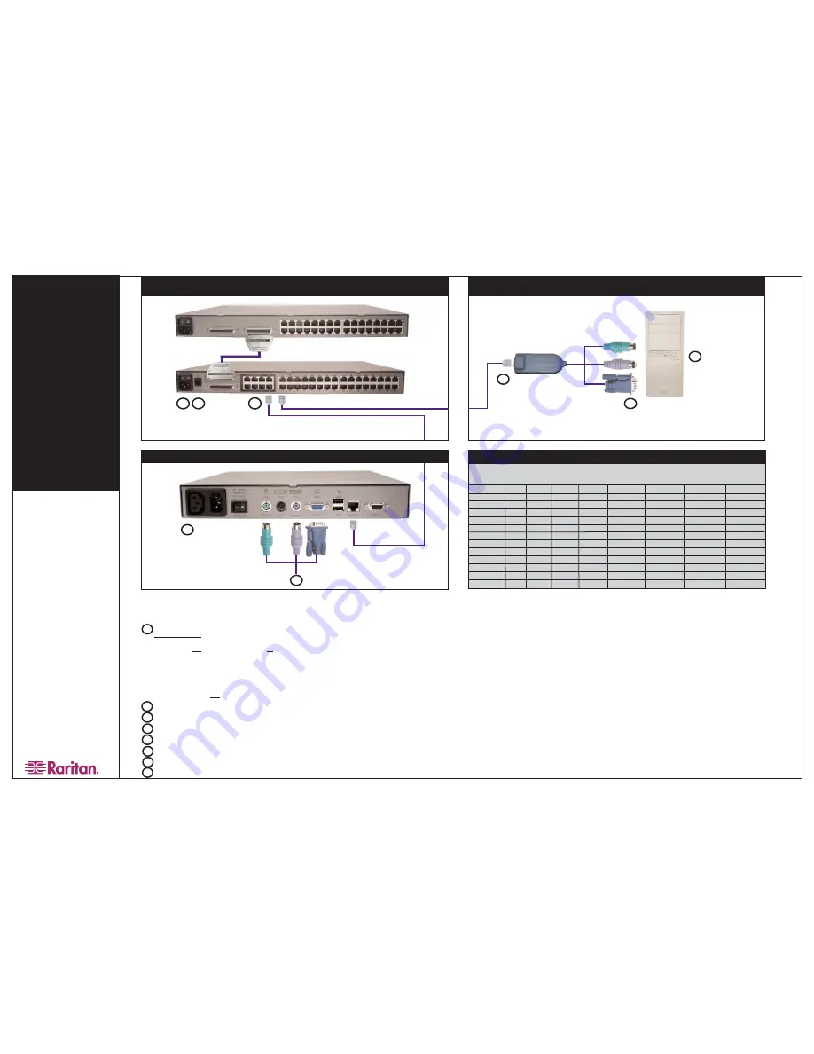
Part
PS/2
SUN
USB
Serial
Video
Local Ports
Firmware
Power Control
Upgradeable
P2CIM-PS2
X
HD15
X
UKVMC
X
HD15
X
UKVMP2
X
HD15
UKVMP-x330
X
HD15
UKVMC-x330
X
HD15
X
UKVMSPD
X
HD15
P2CIM-SUN
X
HD15
X
P2CIM-SUSB
X
X
HD15
X
USKVMPA
X
13W3
USKVMC
X
13W3/HD15
X
P2CIM-USB
X
HD15
X
AUPUSBC
X
HD15
X
AUATC
X
X
Paragon
®
II
Quick Inst
allation and Setup Guide
..
Administrative Setup
Physical Connections
Connect power cord to the Main Switching Unit.
Power ON the Main Switching Unit.
Connect one end of a Category 5e UTP cable to User Port #1 on the back of the Main Switching Unit. Connect the other end of the cable
to the “Cat5 Port” on the back of the User Station (P2-UST)
Connect a power cord to the User Station. Power ON the User Station.
Connect a PS/2 keyboard, mouse, and VGA monitor to the User Station. Power ON the monitor.
Connect one end of a Category 5e UTP cable to Channel Port #1 on the back of the Main Switching Unit (or Stacking Unit, if attached).
Connect the other end of the cable to the RJ45 port on a Computer Interface Module (P2-CIM).
Connect the P2-CIM to server’s keyboard, video, and mouse ports.
Power ON server.
2
1
3
4
5
6
7
8
1.
A Login Menu is displayed on the VGA monitor attached to the User Station. In the user name field type
“a
ad
dm
miin
n” (all lowercase). Press the [E
En
ntte
err] key. In the password field type “rra
arriitta
an
n” (all lowercase). Press the
[E
En
ntte
err] key.
2.
The monitor displays an On-Screen User Interface (OSUI) Selection Menu with the connected server
displayed in green.
3.
Use the [
↑↑]
or [
↓↓]
keys to highlight the green channel and press the [E
En
ntte
err] key.
4.
Normal computer access and operation indicates a successful connection.
IIM
MP
PO
OR
RT
TA
AN
NT
T: A video gain adjustment is available to “focus” the video image (especially when using LCD flat
panel monitors). Activate the OSUI by pressing the [S
Sc
crro
ollllL
Lo
oc
ck
k] key twice rapidly. Use the numeric key pad [+
+]
and [--] keys to adjust the video image until it appears “in focus.”
Please consult the Paragon II User Manual for more information on Paragon II installation, setup, and operation.
Rev. B January 2004 255-30-6010
3
7
8
IIM
MP
PO
OR
RT
TA
AN
NT
T: All computers and Paragon II components must be powered OFF prior to installation.
MAIN SWITCHING UNIT
(P2-UMT1664M, P2-UMT832M, P2-UMT442,
P2-UMT242) AND STACKING UNIT (P2-UMT1664S, P2-UMT832S)
COMPUTER INTERFACE MODULE (CIM)
MULTI-PLATFORM CIM TABLE
4
5
6
1
2
USER STATION (P2-UST)
O
Op
pttiio
on
na
all S
Stta
ac
ck
kiin
ng
g S
Su
up
pp
po
orrtt::
-- Connect power cord to a Stacking Unit.
- Connect one end of a stacking cable to the "Expansion Port Out" on the back of the Stacking Unit. Connect the other end of the cable to the "Expansion Port" on the
Main Switching Unit. N
No
otte
e:: If installing the P2-UMT1664M, use two stacking cables. Connect one stacking cable to the P2-UMT1664S “Out A” port and connect the
other end to “Expansion Port In” on the P2-UMT1664M. Connect the other stacking cable to the P2-UMT1664S “Out B” port and connect the other end to the remain-
ing “Expansion Port In” on the P2-UMT1664M.
- Power ON all switching units.
- On the front panel LCD of the Main Switching Unit:
= Press the F
FU
UN
NC
C button and use the [
↑↑]
and [
↓↓]
keys to select "Stacking Support." Press the E
EN
NT
T button.
= Select the total number of Stacking Units desired (0-3). Press the E
EN
NT
T button.
- On the front panel LCD of the Stacking Unit:
= Press the F
FU
UN
NC
C button and use the [
↑↑]
and [
↓↓]
keys to select "Set Stack ID." Press the E
EN
NT
T button.
= Assign the Stacking Unit ID using the [
↑↑]
and [
↓↓]
keys. E
Ea
ac
ch
h S
Stta
ac
ck
kiin
ng
g U
Un
niitt M
MU
US
ST
T H
HA
AV
VE
E A
A U
UN
NIIQ
QU
UE
E IID
D ((1
1--3
3))!!
= Press the E
EN
NT
T button. N
No
otte
e:: Sequential order is not necessary.


