

Specifications
The
physical
specifications
for
the
RBT
‐
8100
Wireless
Switch
are
listed
in
Table 1
.
Ensure
that
the
environmental
requirements
are
within
the
ranges
described
in
Table 2
.
Chassis and Software Installation Information
This
document
is
only
intended
as
a
quick
start.
Refer
to
the
RoamAbout
RBT
‐
8100
Wireless
Switch
Installation
Guide
for
hardware
(specifications,
regulatory)
and
software
installation
information.
The
latest
RoamAbout
documentation
is
available
from
http://www.enterasys.com/support/manuals
.
Electrical Hazard:
Only qualified personnel should
perform installation procedures.
Table 1 Physical Specifications
Parameter
Width
Height
Depth
Approximate
Specification
430 mm
(16.93 in.)
87.5 mm
(3.445 in.)
672 mm
(26.457 in.)
Table 2 Environmental Specifications
Parameter
Description
Operating Temp.
10°C to 35°C (50°F to 95°F) with the maximum
rate of change not to exceed 10°C per hour
Non-Operating Temp.
40°C to +70°C (104°F to 158°F)
Altitude
-60 meters (-197 feet) below sea level to 4000
meters (13,123 feet) above sea level
Non-Operating Humidity 90%, non-condensing @ 35°C (95°F)
Acoustic noise
Sound Pressure: 55 dBA (Rackmount) in an idle
state at typical office ambient temperature (23
+/- degrees C)
Sound Power: 7.0 BA in an idle state at typical
office ambient temperature (23 +/- 2 degrees C)
Operating Shock
No errors with a half sine wave shock of 2G
(with 11 millisecond duration)
Package Shock
Operational after a 24-inch free fall, although
cosmetic damage may be present (Chassis
Weight 40–80 lbs)
ESD
+/-15kV per Intel Environmental test
specification
System Cooling
Requirement in BTU/Hr
1826 BTU/hour
Connecting the Cables
Connect
your
I/O
cables
as
shown
in
Figure 1
and
press
the
power
button.
Refer
to
the
RoamAbout
RBT
‐
8100
Wireless
Switch
Installation
Guide
for
additional
instructions
on
setup.
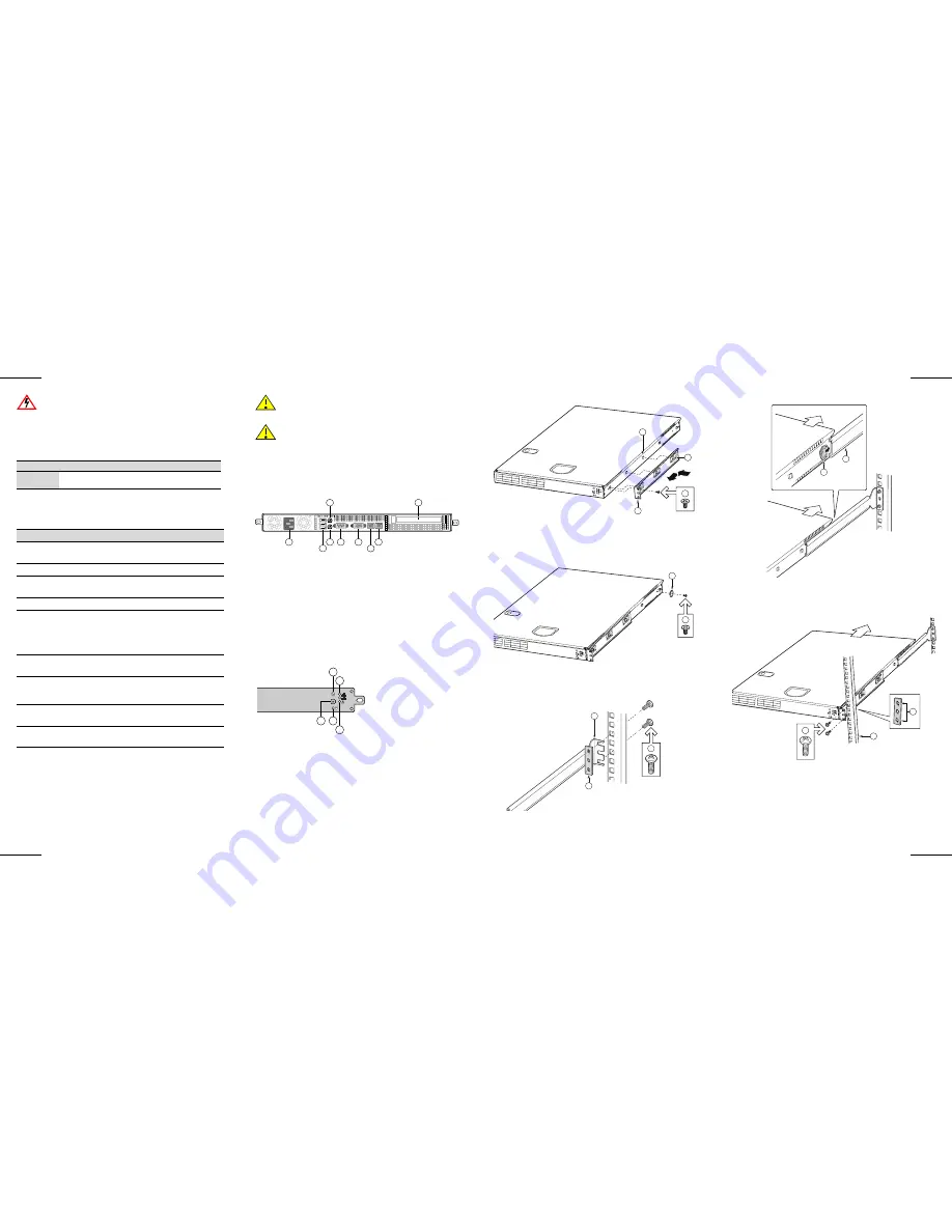
Figure 1 Back I/O Ports and Features
Front Panel Controls and Indicators
Front
panel
LED
indicators
and
their
descriptions
are
shown
in
Figure 2
.
Figure 2 Front Panel Indicators
Mounting in a Four-Post System
The
bracket
kit
allows
you
to
install
the
RBT
‐
8100
Wireless
Switch
into
most
four
‐
post
rack
and
cabinet
systems.
The
only
tool
required
is
a
Phillips
screwdriver.
For
instructions
on
mid
‐
mounting
in
a
two
‐
post
rack
system,
refer
to
the
RoamAbout
RBT
‐
8100
Wireless
Switch
Installation
Guide
.
1. Attach
the
chassis
brackets
to
the
chassis
as
in
Figure 3
.
Caution:
Changes or modifications made to this device which are
not expressly approved by the party responsible for compliance
could void the user’s authority to operate the equipment.
Caution:
Ensure that you wear the ESD (Electrical Static
Discharge) strap during the installation.
A
B
D E
F
G
H
C
I
A
. AC power connector
B
. (
Not supported
)
C
. (
Not supported
)
D
. (
Not supported
)
E
. Serial port A
F
. (
Not supported
)
G
. NIC 1 connector (1 Gbit)
H
. NIC 2 connector (10/100 Mbit)
I
. PCI card bracket (full height)
1
2
B
C
D
E
A
A.
Power button and power
LED
B.
Network activity LEDs
(NIC 1, NIC 2)
C.
System fault LED
D.
Hard drive activity LED
E.
Reset button
Figure 3 Installing Bracket in Front-Mount Position
2. Attach
disks
to
chassis
as
shown
in
Figure 4
.
Figure 4 Attaching Disk to Chassis
3. Attach
rear
brackets
to
rear
posts
as
shown
in
Figure 5
.
Figure 5 Attaching Rear Bracket to Rear Post
4. Install
the
chassis
in
rack
as
shown
in
Figure 6
.
D
B
C
A
A.
Chassis bracket in front mount position
B.
Bracket holes
C.
Chassis tabs
D.
#6-32 x 3/16-inch screw
A
B
A.
Chassis disk
B.
#6-32 x 3/16-inch screw
B
C
A
A.
#10-32 x 1/2-inch screw
B.
Nut bar
C.
Rear bracket
Figure 6 Installing Chassis in Rear Brackets
5. Attach
the
chassis
brackets
to
the
front
posts
as
shown
in
Figure 7
.
Figure 7 Attaching Front Bracket to Front Post
Initial Configuration
Once
your
RBT
‐
8100
is
physically
installed,
you
can
configure
it
quickly
using
the
quickstart
command,
which
runs
an
interactive
script
that
prompts
you
for
required
information
and
lists
the
default
if
applicable.
Refer
to
the
RoamAbout
RBT
‐
8100
Wireless
Switch
Installation
Guide
for
information
about
other
initialization
options.
B
A
A
.Chassis disk
B.
Rear bracket
A
C
B
A.
Front post
B.
Screw
C.
Spacer
17x8.5
with
bleed


