


Chapter 1
Setting Up the ReadyBoard 800
8
QuickStart Guide
ReadyBoard 800
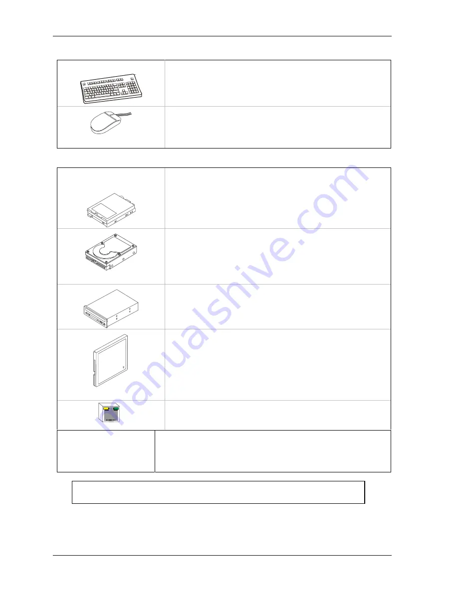
Connecting Peripherals
10) Connecting I/O peripherals
•
Connect the Keyboard to the PS/2 connector with the keyboard icon on
the Y-cable attached to J19.
•
If your are using a USB keyboard, connect it to the USB 0 connector
(lower USB on J18) on the edge of the ReadyBoard 800.
•
Connect the mouse cable to the PS/2 connector with the mouse icon
on the Y-cable attached to J19.
•
If your are using a USB mouse, connect it to the USB 1 connector
(upper USB on J18) on the edge of the ReadyBoard 800.
Connecting Boot Devices
11) Connect the OS boot
device(s)
•
Use one of the seven options listed here to connect an (OS) boot
device(s) to the ReadyBoard 800:
a.
Connect a floppy disk drive(FDD) to the floppy drive only cable
connected to J10 on the edge of the ReadyBoard 800.
Or
Connect a USB floppy drive to one of the USB ports,
Or
b.
Connect an IDE hard disk drive (HDD) to a free connector on the
primary IDE cable (J6) on the edge of the ReadyBoard 800.
Or
, Connect a USB hard disk drive to one of the USB ports,
Or
∗
Ampro does not recommend using a preinstalled OS on a HDD
to boot and load the operating system. See Note with Step 17.
c.
Connect a CD-ROM drive to an available connector on the
primary IDE cable (J6) on the edge of the ReadyBoard 800.
Or
Connect a USB CD-ROM to one of the USB ports,
Or
Compact Flash (CF) Card
d.
Install a compact flash (CF) card with a bootable OS into the
compact flash socket (J23) located on the underside of the board.
Instructions and limitations for installing the compact flash card into
the socket (J23) on the ReadyBoard 800 are provided in Chapter 2,
Installing ReadyBoard 800 Options
later in this manual.
∗
Ampro does not recommend using a preinstalled OS on a CF card to
boot and load the operating system. See Note with Step 17.
Ethernet Connection
e. Connect an Ethernet cable to Ethernet 1 (J16, LAN 1) for the LAN
Boot feature. Refer to the LAN Boot Notes at the end of this
chapter for more information.
12) Verify Jumper Settings
•
Check the jumper settings before applying power, since one of the
jumpers may have fallen off in transit.
•
Refer to Figure 1-4 for jumper locations and the jumper settings found
in Table 1-1 at the end of this chapter for the default jumper settings.
NOTE
For the most current Hardware and BIOS Information, refer to the
Hardware Release Notes provided as hard copy in the shipping container.


