


45
Electric Actuator
OMMG00012
Rev 12 – NOV 2019
4.7
Slacken the nut on the mechanical end stop screw furthest from the
handwheel, and turn the screw counter-clockwise by approximately
10 turns.
4.8
Turn the handwheel 2 turns clockwise, and check that the port has
not started to open. If it has, then turn the handwheel counter-
clockwise until the port is just closed.
4.9
On the mechanical end stop adjuster furthest from the handwheel,
turn the screw clockwise until it stops. Tighten the nut.
CAUTION
Adjustment of the limit switches affects the calibration of the optional
Positioning Electronics Unit. If fitted, it must be re-calibrated before
the actuator is brought into service (refer to OMM47962X00013).
5
If fitted, calibrate the positioning electronics unit (refer to the Positioning
Electronics Unit Manual).
6
Energise the actuator power supply and control circuits and check for
correct operation.
4.8.6
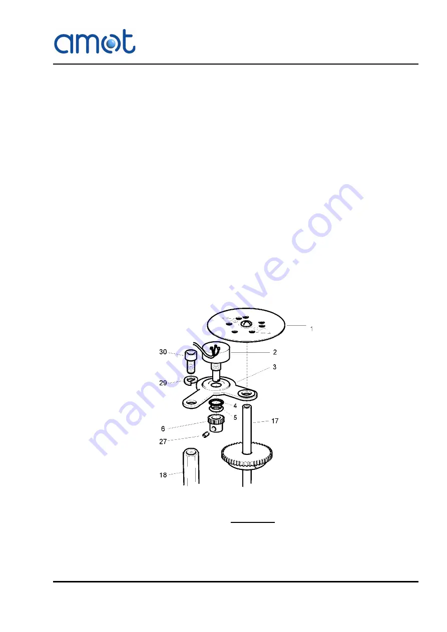
Potentiometer Replacement
Replace the potentiometer as follows (refer to Fig 14, page 45):
Fig 14
Potentiometer Assembly
WARNING
Lethal voltages are exposed when the actuator cover is removed,
presenting an electric shock hazard to personnel. Electrical power
supplies must be isolated from the actuator before the cover is
removed.
Summary of Contents for 10GEF
Page 2: ......
Page 14: ...14 System Overview Rev 12 NOV 2019 OMMG00012...
Page 52: ...52 Electric Actuator Rev 12 NOV 2019 OMMG00012...
Page 54: ...54 PID Controller Rev 12 NOV 2019 OMMG00012...
Page 64: ...64 System Integration Rev 12 NOV 2019 OMMG00012 Fig 22 System Wiring Diagram 8072D Controller...
Page 67: ...67 System Integration OMMG00012 Rev 12 NOV 2019...
Page 68: ...68 System Integration Rev 12 NOV 2019 OMMG00012...
Page 74: ...74 Technical Data Rev 12 NOV 2019 OMMG00012 9 1 1 Valve Bore Fig 25 Valve Selection Curve...