17
Vessel selection according to
SKWI 93-1
It must be possible for the ex-
pansion vessel to take in at least
the calculated volume
Vnom
(given in litres).
The typical intake volumes of
the individual tank sizes can be
read directly from
table
2
and
thus the suitable tank can be de-
termined. When making the se-
lection, it must be ensured that
the system's values for
Hp
and
Pact
respectively are within the
threshold values in the table
.
Other threshold values are pos-
sible. Generally, Boyle-Mari-
otte's gas law applies. This is
based on the premise that the
product of volume and pressure
in the pressure tank is to remain
constant in all operational situa-
tions. As Pneumatex tanks have
no volume-restricting fittings,
the gas law can be applied for
the tank, in the form
Vs ∙ Pt =
Ve∙ Pe
for all special cases, un-
til the maximum construction
pressure (Pcons = 6 bar) has
been reached. Here, the follow-
ing applies:
Vs = system volume of the tankwhen
empty on the water side.
Ptank = pre charge pressure at the
tank (P absolute value).
Ve = final volume of air content, i.e.
difference between total tank vol-
ume and water volume taken in.
Pe =
final pressure in tank, which aris-
es if the volume Ve is reached (P
absolute value).
In all cases, the applicable official
regulations must be adhered to!
Expansion vessel calculation
Calculation
For correct dimensioning of an
expansion vessel, the following
system data must be known:
-
Total system content VS,
(i.e. the
sum of the content of any stor-
age tanks, pipes, radiators, etc.
in the solar system).
-
Maximum supply tempera-
ture tsupply
for the heating
system's dimensioning condi-
tions.
-
System's static height Hp,
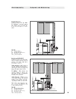
i.e.
height from the centre of the
tank to the system's highest
bleed point
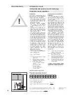
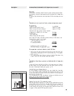
(cf. fig.).
For systems with a maximum
supply temperature above boil-
ing point at atmospheric pres-
sure, the saturation pressure
at the relevant system compo-
nent is to be taken into account
as well as the static height.
-
Construction pressure Pcons
of the most important system
components, which must be
greater than or equal to the
safety valve's
activation pres-
sure Pact
whereby any static
height differences must be
taken into account.
-
Expansion volume Vnom
This is to be calculated accord-
ing to the formula:
Vnom
=
VS
∙F∙x (litres).
V S
= total system content in litres
when cold
F = thermal expansion factor
according to tavg
(see tab. 1)
x = safety margin factor
x = 3; up to 30kW nominal
power
x = 2; 30 to 150kW
nominal
power
x = 1.5; over 150kW
nominal
power
Example calculation: page 20/21
!
II Commissioning
IIc Expansion vessel
Intrinsically safe system, see also next page
Thermal expansion factor F
tavg = 30 °C 40 °C 50 °C 60 °C 70 °C 80 °C 90 °C 100°C 110°C
F =
0.004 0.008 0.012 0.017 0.022 0.029 0.035 0.043 0.051
Assumed filling temperature 10°C = t1
Tsupply = supply temperature °C
Treturn = return temperature °C
tavg = average water temperature in the system =
t
treturn
2
min. required pre charge pressure in tank = Hp + 0.5 bar
min. required activation pressure SV Pact = Pwork + A - B
normal working pressure (Pwork) =
Pact
1.3
EXT
= expansion vessel
SV1
= safety valve

