16
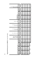
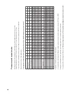
Sugg
est
ed dimensions f
or O
WR 20
(rough estimates)
Collector orientation & roof angle
Number of OWR 12
per collector field
Active absorber area
Volume flow
in the collector field
Pressure loss
in the collector field
Pipe materials
Pipe dimensions
at a pipe length of:
Heat carrier liquid
Tyfocor LS / canister 20 ltr
.
S
outh
30°
-55°
SE / SW
30°
-55°
S
outh
<30°/>55°
SE / SW
<30°/>55°
Stk.
m
2
l/min
kPa
up to 2 x
10.0
m
up to 2 x
15.0
m
up to 2 x
20.0
m
ca.
Number of per
sons for hot process w
ater:
2-3 P
er
s.
30
0 ltr
.
2-3 P
er
s.
30
0 ltr
.
2-3 P
er
s.
30
0 ltr
.
1 P
er
s.
20
0 ltr
.
1
5.5
1.
7
0.6
CU
SR
18x1
.0
15x½"
18x1
.0
15x½"
18x1
.0
15x½"
3
5 P
er
s.
40
0 ltr
.
5 P
er
s.
40
0 ltr
.
5 P
er
s.
40
0 ltr
.
2-4 P
er
s.
30
0 ltr
.
2
10.9
3.4
1.
3
CU
SR
18x1
.0
15x½"
18x1
.0
15x½"
18x1
.0
15x½"
3
6 P
er
s.
50
0 ltr
.
6 P
er
s.
50
0 ltr
.
6 P
er
s.
50
0 ltr
.
6 P
er
s.
40
0/50
0 ltr
.
3
16.4
5.1
4.2
CU
SR
18x1
.0
20x¾"
18x1
.0
20x¾"
18x1
.0
20x¾"
4
6-8 P
er
s.
750 ltr
.
6-8 P
er
s.
750 ltr
.
6-8 P
er
s.
750 ltr
.
6 P
er
s.
50
0 ltr
.
4
21
.8
6.8
8.9
CU
SR
18x1
.0
20x¾"
18x1
.0
20x¾"
18x1
.0
20x¾"
4
8 P
er
s.
750 ltr
.
8 P
er
s.
750 ltr
.
8 P
er
s.
750 ltr
.
7 P
er
s.
750 ltr
.
5
27
.3
8.5
16.1
CU
SR
18x1
.0
20x¾"
18x1
.0
20x¾"
22x1
.0
25x1"
5
10 P
er
s.
10
0
0 ltr
.
10 P
er
s.
10
0
0 ltr
.
10 P
er
s.
10
0
0 ltr
.
8 P
er
s.
750 ltr
.
6
32.8
10.2
26.2
CU
SR
22x1
.0
25x1"
22x1
.0
25x1"
28x1
.5
25x1"
5
Fully integrated collector
hydraulics (fch)
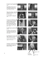
The OWR 12 has fully integrated
1/2’’ collector hydraulics (fch),
with a third connection, includ-
ing sensor wells installed on
both sides. Hydraulic connec-
tion is freely selectable.
Conventional one-side and al-
ternating-side connections
With conventional connection,
the 3rd connection is closed
off with a wind-resistant plastic
cap. Two blind covers close off
the collector array. The connec-
tion can also be realised one-
sided (on the right-hand side or
on the left-hand side).
Tichelmann
With Tichelmann connection,
there is cold flow through the
internal return pipe. The blind
covers are applied to the first
and last collectors as shown.
Corresponding one-sided con-
nection on the right-hand side.
Large-scale systems (Tichelmann)
Large-scale systems, e.g. more
than 6 OWR 20 collectors in a
row, can be connected together
in the centre of the array for
quick, low-loss yields.
II Commissioning
IIb Hydraulic connections
Do not fill the system in direct sunlight.
Danger of steam hammering!
Sensor
Attention!
We recommend connection
according to “A” and “B”.
The sensor is connected to the return side of the collector array.
(see pages 9 and 12/13)
C
Collector outlet /
hot
B
Collector inlet /
cold
A
Internal
return pipe /
collector inlet
U-pipe from A to B
A
B
D
Volume flow:
OWR 20: 1,7 l/min
Volume flow:
OWR 20: 1,7 l/min
Volume flow:
OWR 20: 1,7 l/min
max. 2 x 6 OWR 20
max. 6 OWR 20
max. 8 OWR 20
C
not possible
U-bend
Blind cover
(3/4” brass)
Expansion joint
Plastic caps

