2
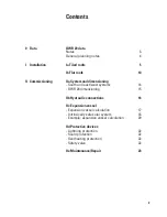
Contents
0 Data
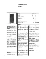
OWR 20 data
Notes
3
General planning notes
4
I Installation
Ia Tiled roofs
5
Ib Flat roofs
10
II Commissioning
IIa System and dimensioning
- South and east/west systems
14
- OWR 20 dimensioning
15
IIb Hydraulic connections
16
IIc Expansion vessel
- Expansion vessel calculation
17
- Intrinsically safe solar system
18
- Example: expansion vessel calculation
20
IId Protective devices
- Lightning protection
22
- Scald protection
22
- Overheating protection
22
- Safety valve
22
IIe Maintenance/Repair
23
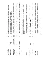
Quic
k mounting guide f
or installation personnel:
Pa
g
e
The solar collect
or syst
em is t
o be installed b
y qualified personnel only
.
Pac
kaging
+ T
ranspor
t:
3
Store collector
s cor
rectly; don
’t throw the pac
kaged bo
xes.
Transpor
t collector
s in pac
kaging only
.
Collector mounting:
T
iled roof
5-9
W
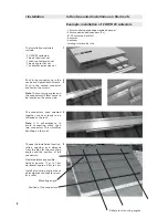
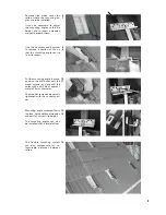
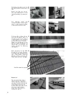
ork preparations as shown on page 5-8, assembly as shown on page 8-9.
Flat roof
10-1
3
W
ork preparations as shown on page 1
0-1
1, assembly as shown on page 1
2-1
3.
Collector connections
to a collector field:
Compensator
s and
8/9/1
2
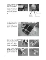
The screw connections of the compensator
s are to be tightened with a tightening torque of max. 1
5 Nm.
U-pipes/Blind caps
8/9/1
2
The included high temperature flat g
ask
ets must be used.
S
ensor placement
in the collector field:
S
ensor
9/1
3
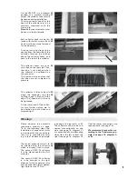
The collector sensor must be inser
ted into the sensor well all the w
ay (1
8-1
9 cm) at the solar liquid outlet
(flow).
The sensor cable must be fixed to av
oid shif
ting (e.g. snow load, animals).
Connecting the solar pipes with
the solar collector field
S
olar pipes
9/1
3
At
tention is to be paid to the male connector
s, shown in the pictures on page 9/1
3.
The connection labeled
„hot“ is the flow
. The connections must not be confused.
Expansion vessel
The cor
rect connection of the expansion vessel is determined by the site management.
The pre c
harge
pressure must be adjusted before the filling of the system.
Expansion vessel pre c
harge pressure = Ok collector up to middle of expansion vessel in bar + 0.5 bar
,
but at least at 1
.0 bar
P
ressure test
Af
ter the mounting of the collector field, solar pipes, pump groups and the heat consumer
s the system
must be c
hec
ked for absolute leakproofness (e.g. compressed air at 2-3 bar for at least 2-3 hr
s.),
or with fluid (e.g. 4 bar for at least 2-3 hr
s.)
Filling of the solar system
resp.
21 16
Connect filling station to
A
O +
A1
. Fill system slowly
. The bleed valve at the pump station is closed.
R
emo
ve flow meter
.
Do not fill in dir
ect sunshine!
Flushing the system
resp.
21 16
The flushing cleans the system and bleeds the whole facility
.
This flushing is to be done thoroughly and
without inter
ruption.
S
olar controller:
The controller set
tings are to be set by the site management. Chec
king of the cor
rect electric connections.
Commissioning:
Af
ter initial star
t-up an acceptance testing protocol is to be completed, dated and signed by the installer
and by the operator
. This document belongs to the operator of the facility
.
IMPOR
TANT
:
Don't use an
y zinced components in the solar cir
cuit!
Tyf
ocor LS is a complet
e mixt
ur
e.
Don't mix with w
at
er!


