12
17
18
16
19
20
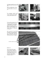
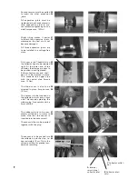
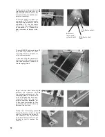
The final step is to fasten the
pivot bolts at the lower end of
the supports. The standing sup-
ports are pre-configured in the
factory for approximately 40°.
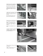
The collector can be mounted at
a more shallow angle by moving
the lower end inwards. Moving
the upper end inwards makes
the angle steeper. The supports
can also be cut to length in
order to achieve an even more
shallow angle.
The central connecting expan-
sion joint is to be screwed tight
on one side. Hydraulic connec-
tions: see page 18
Another support is to be di-
mensioned for installation of
the second collector. Follow the
same procedure as for the first
collector.
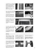
The central connecting expan-
sion joint is to be tightened us-
ing two spanners diametrically
opposed.
The other two expansion joints
are also to be installed. Dur-
ing insertion, it is necessary to
squeeze the expansion joints
together a little.
Screw the U-bend in place. With
the blind cover, all connections
are now sealed (torque max. 15
Nm).
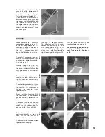
The sensor is to be inserted on
the collector's input and output
side. Pierce the rubber plug, for
example with a 5mm drill bit.
The rubber plug is to be com-
pletely pulled out, in order to
make sure that the sensor is
inserted into the sensor well.
The sensor is then to be inserted
together with the plug.
21
22
23
24
Warning!
Please observe the hydraulic
connection variants on page 16.
In the following steps, the in-
stallation of expansion joints is
described for the case where
the unit is connected accord-
ing to the Tichelmann principle
(see page 16, diagram A or B).
The collectors can also be con-
nected conventionally on one
side (see page 16, diagram C)
or conventionally on alternating
sides from the left or from the
right (see page 16, diagram D).
Only the lower connections are
required here (see page 16).
We recommend connection ac-
cording to the Tichelmann prin-
ciple (see page 16, diagram A
or B).


