932512A / 0114
ORTEC
®
EASY-NIM
™
928 Suite
9
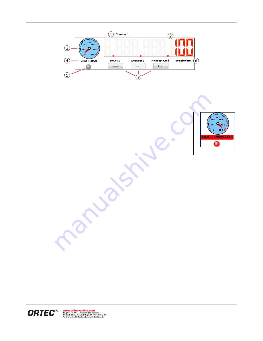
Figure 7. Counter Readout Features.
3) Alarming Counter/Rate Meter. The analog meter can be set as logarithmic or linear. The alarm threshold is
variable and can be set to create a hardware alarm signal for external equipment
(see the next section).
4) Count rate meter (
CRM
), in counts per second (cps). If an alarm is triggered, based
on the
Alarm threshold
entry discussed in Section 3.3.4.4, this field flashes red
(Figure 8). In addition, if the
Play sound when alarm triggered
checkbox is marked
on the setup screen, an audio alarm sounds. The count rate can be read from user-
written software.
5) Data acquisition indicator. When counter is enabled, the “LED” blinks red
(Figure 8).
6) Counter settings indicators display a mnemonic of the parameters selected on the Instrument Settings screen
(discussed in the next section).
I
= Counter input,
G
= Gate input,
R
= Reset input,
E
= Enable input.
7)
Enable
,
Disable
, and
Reset
buttons. If the
Counter Enable
on the setup screen input is set to
Software
Control
, the
Enable
and
Disable
buttons on this screen become active, allowing you to manually start and
stop the counter. If the
Counter Reset
input is set to
Software Individual Reset
, the
Reset
button on this
screen becomes active, allowing you to manually zero the counter. When a counter is enabled, it remains
active until disabled. Data acquisition will suspend when all counters are full or an associated timer preset
lapses, but clicking the corresponding
Reset
button immediately zeros the counter and restarts acquisition.
The main features of the timer readouts are shown in Figure 9.
1) User-defined timer
Friendly name
; can be changed on the setup screen (discussed in the next section).
2) Timer value digital display. Maximum value is 4294967295, readable with user-written software.
3) Timer settings indicators display a mnemonic of the parameters selected on the Instrument Settings screen
(discussed in the next section).
TB
= Time base,
P
= Time preset,
R
= Reset input,
E
= Enable input.
4)
Enable
,
Disable
, and
Reset
buttons. If the timer
Enable input
is set to
Software Control
, the
Enable
and
Disable
buttons on this screen become active, allowing you to manually start and stop the timer from the
application screen. If the timer
Reset input
is set to
Software Individual Reset
, the
Reset
button on this
screen becomes active, allowing you to manually zero the timer value. When a timer is enabled, it remains
active until disabled. Data acquisition will suspend when the timer preset lapses or when the associated
Figure 8.


