background image


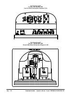
American-Lincoln

®


Operator's Manual - Encore

2

 S28/D28/S33/D33/S38/D38 WB                                                     - 99 -

American Lincoln

®

Encore

 D28/D33/D38 WB

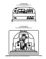
Control Panel Connection Diagram 11/04

American Lincoln

®

Encore

2  

 D28/D33/D38 WB

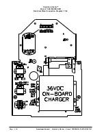
(Front of Machine) Connection Diagram 11/04

Summary of Contents for Encore D28 WB

Page 1: ...ne before using it If your operator s cannot read English have this manual explained fully before attempting to operate this machine Si Ud o sus operadores no pueden leer el Inglés se hagan explicar este manual completamente antes de tratar el manejo o servicio de esta máquina All directions given in this book are as seen from the operator s position at the rear of the machine For new books write ...

Page 2: ...0 947 n 6 105 192 n 5 383 251 n 6 493 896 machines Deluxe LEA ESTE MANUAL Este manual contiene información importante acerca del uso y la seguridad de la máquina Si no lee el manual antes de utilizar su máquina American Lincoln o de intentar realizar los procedimientos de reparación o mantenimiento de la misma usted o el resto del personal podrían sufrir lesiones asimismo podrían producirse daños ...

Page 3: ... A Floor 54 Maintenance 56 How To Correct A Problem 66 Common Error Codes D28 D33 D38 69 Accessories 72 Section II Parts and Service Manual Solution Tank Assembly 76 Parts List 77 Recovery Tank Assembly 78 Parts List 79 Electrical Panel Assembly S28 S33 S38 80 Parts List 81 Electrical Panel Assembly D28 D33 D38 82 Parts List 83 Control Panel Assembly 84 Parts List 85 Squeegee Swing Arm Assembly 86...

Page 4: ... Mantenimiento 57 Corrección de problemas 67 Códigos de error comunes D28 D33 D38 70 Accesorios 73 Sección II Manual de repuestos y servicio Montaje del depósito de solución 76 Lista de piezas 77 Montaje del depósito de recuperación 78 Lista de piezas 79 Montaje del panel eléctrico S28 S33 S38 80 Lista de piezas 81 Montaje del panel eléctrico D28 D33 D38 82 Lista de piezas 83 Montaje del panel de ...

Page 5: ...entretien Montage du réservoir de solution 76 Nomenclature des pièces 77 Montage du réservoir de récupération 78 Nomenclature des pièces 79 Montage du panneau électrique S28 S33 S38 80 Nomenclature des pièces 81 Montage du panneau électrique D28 D33 D38 82 Nomenclature des pièces 83 Montage du panneau de commandes 84 Nomenclature des pièces 85 Montage du bras pivotant de la raclette 86 Nomenclatur...

Page 6: ...cabezado ADVERTENCIA usted o el resto del personal pueden sufrir lesiones también pueden producirse daños a la propiedad Lea y respete todas las indicaciones de ADVERTENCIA que se encuentran en el manual de instrucciones y en la máquina PRECAUCIÓN Si no se leen y respetan todas las instrucciones que aparecen bajo el encabezado PRECAUCIÓN pueden producirse daños en la máquina y en otras propiedades...

Page 7: ...la en funcionamiento DANGER L utilisation d une machine qui n est pas entièrement assemblée est susceptible de provoquer un accident ou d entraîner des dommages N utilisez pas cette machine avant qu elle ne soit complètement assemblée Inspectez soigneusement la machine avant utilisation DANGER Machines can cause an explosion when operated near flammable materials and vapors Do not use this machine...

Page 8: ...uis l arrière WARNING This machine is heavy Get assistance before attempting to transport or move it Use two able persons to move the machine on a ramp or incline Always move slowly Do not turn the machine on a ramp If operating machine on a gradient over 2 do not stop turn or park Read the Procedures For Transporting in this manual before transporting ADVERTENCIA La máquina es pesada Obtenga ayud...

Page 9: ... et à l humidité Veillez à ce que les composants électriques de la machine soient toujours secs Essuyez la machine après chaque utilisation Stockez la machine dans un bâtiment à l abri de l humidité WARNING Operating a machine without observing all labels and instructional information could result in injury or damage Read all machine labels before attempting to operate Make sure all of the labels ...

Page 10: ...ion des eaux usées De même une réglementation municipale et nationale relative à l élimination des eaux sales peut être en vigueur dans votre région Comprenez et respectez la réglementation en vigueur dans votre région Soyez conscients des dangers que constituent pour l environnement les produits chimiques que vous éliminez CAUTION Use of this machine to move other objects or to climb on could res...

Page 11: ... de 33 pulgadas de ancho El modelo Encore2 28 utiliza dos cepillos o almohadillas para limpiar un recorrido de 28 pulgadas de ancho Una escobilla de goma limpia el piso mientras el motor de vacío quita la solución sucia del piso y todo esto en una sola pasada Las fregadoras automáticas Encore2 38 33 y 28 se entregan completas con seis baterías de 6 voltios cinco cables conectores de baterías dos c...

Page 12: ... Shipping Weight 1328 lbs 602kg 1318 lbs 598kg 1308 lbs 593kg w batteries 330AH Noise 76 5 dBA 76 5 dBA 76 5 dBA Vibration 2 5 m s2 2 5 m s2 2 5 m s2 SPECIFICATIONS Model S38 S33 S28 Motor Vac 1 HP 74kw three 1HP 74kw three 1HP 74kw three stage tangential stage tagential stage tagential discharge discharge discharge Power Supply 36 volt 6 6V batteries 36 volt 6 6V batteries 36 volt 6 6V batteries ...

Page 13: ... de envío 1328 lbs 602kg 1318 lbs 598kg 1308 lbs 593kg con baterías 330AH Ruido 76 5 dBA 76 5 dBA 76 5 dBA Vibraciones 2 5 m s2 2 5 m s2 2 5 m s2 ESPECIFICACIONES Modelo D38 D33 D28 Motor de vacío de 1 HP 67kw de 1HP 67kw de 1HP 67kw de descarga tangencial de descarga tangencial de descarga tangencial de tres etapas de tres etapas de tres etapas Fuente de alimentación 36 voltios baterías de 6 6V 3...

Page 14: ...oids à l expédition 602 kg 598 kg 593 kg avec batteries 330 Ah Niveau sonore 76 5 dBA 76 5 dBA 76 5 dBA Vibration 2 5 m s2 2 5 m s2 2 5 m s2 CARACTERISTIQUES Modèle D38 D33 D28 Moteur d aspiration 1 ch 67 kW 3 temps 1 ch 67 kW 3 temps 1 ch 67 kW 3 temps tangentiel tangentiel tangentiel discharge discharge discharge Alimentation électrique 36 volts 6 batteries de 6 V 36 volts 6 batteries de 6 V 36 ...

Page 15: ... Turn the key switch OFF 11 Fasten the machine to the vehicle How To Remove The Machine From A Van Or Truck 1 Make sure there are no obstructions in the area 2 Make sure the unloading ramp is at least eight 8 feet long and strong enough to support the machine 3 Make sure the ramp is clean and dry 4 Put the ramp in position 5 Unfastenthemachine WARNING The machine is heavy Make sure you use two abl...

Page 16: ...FF apagado 11 Asegure la máquina en el vehículo Sacar la máquina de una furgoneta o un camión 1 Asegúrese de que no haya ninguna obstrucción en el área 2 Asegúrese de que la rampa de descarga tenga al menos 2 4 metros 8 pies de longitud y de que su resistencia sea suficiente para soportar la máquina 3 Asegúrese de que la rampa esté limpia y seca 4 Sitúe la rampa en posición 5 Suelte la máquina ADV...

Page 17: ...commutateur à clé en position OFF 11 Fixez la machine sur le véhicule Retrait de la machine d une camionnette ou d un camion 1 Assurez vous que la zone ne comporte aucun obstacle 2 Assurez vous que le plan incliné fait au moins 2 50 m de long et qu il est suffisamment solide pour supporter le poids de la machine 3 Assurez vous que le plan incliné est propre et sec 4 Mettez le plan incliné en posit...

Page 18: ...D33 S38 D38 WB SYMBOLS USED ON Encore2 S28 S33 S38 Hazard Alert Symbol On Off Key Switch BrushUp Down Solution Control Power Traverse Speed Control AdditionalBrushPressure Charge Battery Meter Warning Label with parking brake Warning Label without parking brake EN ...

Page 19: ... Hazard Alert Symbol On Off Key Switch Squeegee Up Down Solution Control Hour Meter Switch Power Traverse Speed Control BrushUp Down Charge Indicator One Touch Switch Warning Label with parking brake Warning Label without parking brake EN SYMBOLS USED ON Encore2 D28 D33 D38 ...

Page 20: ...38 Símbolo de alerta de riesgo Interruptor de llave On Off encendido apagado Cepillo Arriba Abajo Control de solución Alimentación Control de velocidad de desplazamiento Presión adicional del cepillo Medidor de carga batería Etiqueta de advertencia con freno de estacionamiento Etiqueta de advertencia sin freno de estacionamiento ES ...

Page 21: ... llave On Off encendido apagado Escobilla de goma Arriba Abajo Control de solución Interruptor de cuentavueltas calibrado en horas de trabajo Alimentación Control de velocidad de desplazamiento Cepillo Arriba Abajo Indicador de carga Interruptor de pulsación única Etiqueta de advertencia con freno de estacionamiento Etiqueta de advertencia sin freno de estacionamiento ES ...

Page 22: ...vertissement d un danger Commutateur à clé Marche Arrêt Abaissement relèvement des brosses Niveau de solution Alimentation Contrôle de la vitesse de déplacement Augmentation de la pressiondesbrosses Indicateur de charge des batteries Autocollant d avertissement avec frein de stationnement Autocollant d avertissement sans frein de stationnement FR ...

Page 23: ...er Commutateur à clé Marche Arrêt Relèvement Abaissement de la raclette Niveau de solution Commutateur du compteur horaire Alimentation Contrôle de la vitesse de déplacement Abaissement relèvement desbrosses Indicateur de charge Commutateur One Touch Autocollant d avertissement avec frein de stationnement Autocollant d avertissement sans frein de stationnement FR ...

Page 24: ...ob regulates the flow of cleaning solution to the floor To increase the flow turn the knob clockwise To decrease the flow turn the knob counter clockwise Forward Switch See Figure 1 Item F The forward switch turns the traverse motor on and if the brush motors are in the down position it also activates the brush motors and solution control module Either the right or the left switch can be used Reve...

Page 25: ...American Lincoln Operator s Manual Encore2 S28 D28 S33 D33 S38 D38 WB 25 Figure 1 MACHINE CONTROL PANEL S28 S33 S38 F G B F A H I J K L M N E C D EN ...

Page 26: ...piso Para aumentar el flujo gire la perilla en el sentido de las agujas del reloj Para reducir el flujo gire la perilla en sentido contrario al de las agujas del reloj Interruptor de movimiento hacia adelante consulte la figura 1 elemento F El interruptor de movimiento hacia adelante enciende on el motor de desplazamiento y activa además los motores del cepillo si éstos están en posición down abaj...

Page 27: ...American Lincoln Operator s Manual Encore2 S28 D28 S33 D33 S38 D38 WB 27 Figura 1 PANEL DE CONTROL DE LA MÁQUINA S28 S33 y S38 F G B F A H I J K L M N E C D ES ...

Page 28: ...r le débit tournez la molette dans le sens des aiguilles d une montre Pour diminuer le débit tournez la molette dans le sens inverse des aiguilles d une montre Commutateur de marche avant Cf figure 1F Le commutateur de marche avant permet de mettre le moteur de déplacement en marche Si les brosses sont en position basse il permet également de mettre en marche le moteur des brosses et le module de ...

Page 29: ...American Lincoln Operator s Manual Encore2 S28 D28 S33 D33 S38 D38 WB 29 Figure 1 PANNEAU DE COMMANDE DES MODELES S28 S33 S38 F G B F A H I J K L M N E C D FR ...

Page 30: ...tion to the floor To increase the flow push the solution flow switch in the down position until desired flow is reached To decrease the flow push the solution flow switch in the up position until the desired flow is reached To shut off the solution push the solution flow switch in the up position until no indicators are visible on the display NOTE DO NOT run dry NOTE No solution will flow when the...

Page 31: ...reaker reset buttons are located on the control panel The breakers are located as follows Item L and M Brush Motors 35A Item N Key Switch 5A If a circuit breaker trips determine which motor is not operating and turn the key switch OFF Wait five minutes and push the reset button back in Turn the key switch ON and try again An authorized service person should be contacted if the breaker trips again ...

Page 32: ...en la posición abajo hasta alcanzar el flujo deseado Para reducir el flujo pulse el interruptor de flujo de solución en la posición arriba hasta alcanzar el flujo deseado Para apagar el flujo de solución pulse el interruptor de flujo de solución en la posición arriba hasta que no se visualicen indicadores en la pantalla NOTA NO opere la máquina en seco NOTA La solución sólo fluirá cuando la máquin...

Page 33: ...ontrol Los disyuntores están situados de la siguiente forma Elementos L y M Motores del cepillo 35A elemento N Interruptor de llave 5A Cuando se dispare un disyuntor determine el motor que no está funcionando y gire el interruptor de llave a OFF apagado Espere cinco minutos y pulse el botón de reposición Gire el interruptor de llave a ON encendido y vuelva a intentarlo Si el disyuntor se dispara d...

Page 34: ...ébit désiré soit atteint Pour réduire le débit poussez le commutateur d écoulement de la solution vers le haut jusqu à ce que le débit désiré soit atteint Pour stopper l écoulement de la solution poussez le commutateur d écoulement de la solution vers le haut jusqu à ce que tous les voyants soient éteints sur le panneau de commandes REMARQUE NE PAS faire fonctionner à sec REMARQUE la solution ne s...

Page 35: ...au de commandes Les coupe circuits sont situés aux emplacements suivants Eléments L et M Moteur de la brosse 35 A Elément N Commutateur à clé 5 A Si un disjoncteur se déclenche déterminez lequel des moteurs ne fonctionne plus et mettez le commutateur à clé en position OFF Attendez cinq minutes et appuyez sur le bouton de réinitialisation Mettez le commutateur à clé en position ON et ré essayez Un ...

Page 36: ...rator Battery blinks when low voltage occurs Water droplets off when solution is off and they are flashing when solution is on Arrows indicating vacuum status They are flashing when vac is on and off when vac is off SCREEN1 SCREEN2 Example SCREEN3 Diagnostic The Diagnostic only It will not show unless a fault with the machine occurs When the fault happens the icon and error code will be displayed ...

Page 37: ...uando hay bajo voltaje El goteo de agua está apagado cuando la solución está apagada y parpadea cuando la solución está encendida Flechas que indican el estado de aspiración Parpadean cuando la aspiración está encendida y están apagadas cuando la aspiración está apagada PANTALLA 1 PANTALLA 2 Ejemplo PANTALLA3 Diagnóstico Sólo el diagnóstico No aparece a menos que se produzca un fallo de la máquina...

Page 38: ...outtelettes d eau s éteignent lorsque la solution ne s écoule plus et elles clignotent dans la cas contraire Flèches indiquant l état du dispositif d aspiration Elles clignotent lorsque l aspirateur est en marche et n apparaissent pas lorsqu il est éteint ECRAN1 ECRAN2 Exemple ECRAN3 Diagnostic Destiné au diagnostic uniquement Reste éteint tant que la machine ne présente pas de panne Lorsque la pa...

Page 39: ...American Lincoln Operator s Manual Encore2 S28 D28 S33 D33 S38 D38 WB 39 NOTES ...

Page 40: ...r disconnect the power to the battery to apply the brake There is a mechanical lever located on the brake This lever is an override To manually release the brake rotate the lever toward the rear of machine counter clockwise To return the brake to normal or to apply the brake rotate the lever towards the front of the machine clockwise NOTE If the lever is left in the override position the brake wil...

Page 41: ... apagado del motor de vacío está ubicado en el depósito de recuperación Apaga automáticamente el motor de vacío cuando el depósito de recuperación está lleno ES FR COMMANDES ET FONCTIONNALITES DE LA MACHINE Manette de relèvement de la raclette Modèles Classe S uniquement Cf figures 3a 3b et 3c La manette de relèvement de la raclette est située sous le panneau de commandes à droite Elle permet de r...

Page 42: ...ecoverytank 6 Place the batteries in the solution tank as shown in figures 6a and 6b WARNING Lifting batteries without help could result in an injury Get help to lift the batteries The batteries are heavy WARNING Working with batteries can be dangerous Always wear eye protection and protective clothing when working near batteries NOSMOKING 7 Connect the battery cables between batteries and install...

Page 43: ...rruptor del flotador Instale la abrazadera de apoyo del depósito NOTA Cargue las baterías antes de utilizar lamáquina Installation des batteries Les 28 33 et 38 utilisent six batteries de 6 volts Les batteries sont situées dans le compartiment à batteries sous le réservoir de récupération Pour installer les batteries appliquez la procédure suivante 1 Mettez le commutateur à clé en position ON 2 As...

Page 44: ...ells with distilled water after charging CAUTION Irreversible damage will occur to the batteries if the electrolyte level doesnotcovertheplates Keepthe electrolyte at the correct level CAUTION Machine damage and discharge across the tops of the batteries can occur if the batteries are filled above the bottom of the tube in each cell Do not fill the batteries up to the bottom of the tube in each ce...

Page 45: ... las baterías cargadas PREPARACIÓN DE LA MÁQUINA PARA EL FUNCIONAMIENTO PREPARATION DE LA MACHINE AVANT UTILISATION Entretien des batteries L alimentation électrique de la machine est assurée par des batteries d accumulateurs Les accumulateurs nécessitent un entretien préventif AVERTISSEMENT Travailleravecdesbatteriespeutêtre dangereux Portez toujours des lunettes et des vêtements de pro tection l...

Page 46: ...recovery tank is in the open position The tank can be acci dentally bumped and it may slam shut 3 ConnectthebatterychargerACcordlocatedatthe rearofthemachinetoa15amp min 120Vproperly groundedwallreceptacle 4 Observe indicator light to ensure the charging pro cess has started Flashing light s indicates that the batteries are being charged Steady on green light indicates the batteries are fully char...

Page 47: ...ario cubra por completo con agua destilada PREPARACIÓN DE LA MÁQUINA PARA EL FUNCIONAMIENTO Chargement des batteries AVERTISSEMENT Le chargement des batteries dans une zone sans ventilation adéquate risque d entraîner une ex plosion Afin d éviter tout risque d explosion ne rechargez les batter ies que dans endroit bien ventilé AVERTISSEMENT Les batteries au plomb génèrent des gaz susceptibles d ex...

Page 48: ...tabrushorpaddriverunderthebrushmotorplate See figure 10 7 Alignthelugsonthemotorgimbalwiththeslotsinthe brushgimbal 8 Pull the brush up until the gimbal locks 9 Repeat steps 6 7 and 8 to install the second brush orpaddriver How To Remove The Brushes Or Pad Drivers To remove the brushes or pad drivers from the machine followthisprocedure 1 Turn the key switch ON 2 Put the brush switch in the UP pos...

Page 49: ...a de la máquina 5 Empuje hacia abajo los dos lados del cepillo o impulsor de almohadillas hasta que se liberen las suspensionescardánicas PREPARACIÓN DE LA MÁQUINA PARA EL FUNCIONAMIENTO Installation des brosses ou des entraîneurs de disque Pourinstallerlesbrossesoulesentraîneursdedisquesur la machine appliquez cette procédure 1 Mettez le commutateur à clé en position ON 2 Mettez le commutateur de...

Page 50: ...ou stop and do it some solution can be left on the floor Reprogramming One Touch If you do not want to use the factory default settings you may reprogram the setting by following the procedures below 1 Place the machine in the desired scrub condition by using the one touch and individual switches 2 Press and hold the green one touch button until you see the LCD display flash then release the butto...

Page 51: ...iones deben volver a 4 barias de solución y 2 barias de presión del cepillo NOTA El interruptor de aspiración de la escobilla de goma debe estar en la posición media para que funcionen las configuraciones por omisión OPERACIÓN DE LA MÁQUINA Utilisation du système One Touch Modèles de Classe D uniquement Le nettoyage One Touch est une nouvelle fonction proposée par l autolaveuse autoportée Encore2 ...

Page 52: ...chine To fill the solution tank follow this procedure 1 Remove the solution tank lid See figure 15 2 Fill the solution tank with water 3 Add a cleaning chemical to the water for the correct amount follow the directions shown on the container WARNING Water solutions or cleaning materials used with this type of machine can leave wet areas on the floor surface These areas can cause a dangerous condit...

Page 53: ...la abrazadera e inserte la manguera como se indica en la figura 16 El nivel de solución puede visualizarse desde la parte posterior de la máquina Utilisation de la raclette modèles de Classe S uniquement La raclette essuie le sol tandis que le moteur d aspiration enlève la solution sale du sol Utilisez votre main droite pour abaisser ou relever la manette de commande de la raclette Suivez la procé...

Page 54: ...chinetothe side 8 Whenyoustopthemachine turnthekeyswitch OFF How to Clean a Floor WARNING Water solutions or cleaning materi als used with this type of machine can leave wet areas on the floor surfaces These areas can cause a dangerousconditionfortheoperator or other persons Always put CAU TION signs near the area you are cleaning To clean a floor follow this procedure 1 Put the water and a cleani...

Page 55: ...as 5cm del área ya limpiada NOTA Durante la mayoría de los procedimientos de limpieza aplique y quite la solución en una sola operación OPERACIÓN DE LA MÁQUINA Conduite de la machine REMARQUE Mettez la machine en vitesse lente Cf figure 17 Utilisez la machine dans une zone ne comportant ni meubles ni objets jusqu à ce que vous sachiez faire les choses suivantes 1 Déplacez la machine en ligne droit...

Page 56: ...y the solution tank and recovery tank before doing any maintenance WARNING Keep all fasteners tight TheseMaintenanceProceduresMustBeDoneEveryDay Keep the machine clean it will need fewer repairs and havelongerlife Do These Procedures When You Begin Your Work Period 1 Turn off key switch 2 UnplugchargerfromACoutletandwrapcordaround bracket at rear of machine 3 Makesuretherecoverytanklidisoncorrectl...

Page 57: ...en posición y se hayan instalado correctamente 8 Verifique la instalación de la escobilla de goma y de la manguera de la misma MANTENIMIENTO Limpieza de pisos muy sucios Para limpiar pisos muy sucios siga este procedimiento 1 Aplique solución al piso 2 No baje la escobilla de goma 3 No active el motor de vacío 4 Baje los cepillos y limpie el piso 5 Deje la solución en el piso por el tiempo suficie...

Page 58: ...hthetankorhose Putthe water hose into the drain hose 4 Leavethetanksandthedrainvalvesopentodryinthe air 5 Check the squeegee blade Use a cloth to clean the squeegee blade If the squeegee blade is damaged or worn turn or replace the blade 6 Check and clean the recovery lid gasket Use a mild cleaning solution and rinse the parts in clean water Check the batteries and add distilled water as needed Th...

Page 59: ...e Chargez les batteries Consutez les instructions données dans la section de ce Manuel intitulée Rechargement de la batterie Efectúe estos procedimientos al final del período de trabajo 1 Drene el depósito de solución figura 21 elemento A y el depósito de recuperación consulte la figura 21 Elemento B Para drenar los depósitos siga este procedimiento a Gire el interruptor de llave hasta la posición...

Page 60: ...d acid to battery after installa tion NOTE Alwaysturnoffkeyswitchbeforeservicingthe machine WARNING Always wear eye protection and protective clothing when working near batteries NO SMOKING 1 To inspect batteries tip up recovery tank until it locks in up position See Figure 24 2 Disconnect the batteries Use a cloth and a solution ofammoniaorbicarbonateofsodatowipethetopofthe batteries Cleanthebatt...

Page 61: ...te la figura 25 6 Controle la presión del neumático La presión del neumático debe ser de aproximadamente 50 psi Ces opérations de maintenance doivent être faites toutes les semaines AVERTISSEMENT L entretien et les réparations ne doivent être effectués que par un technicien agréé Videz toujours les réservoirs de solution et de récupération avant toute opération de maintenance Veillez à ce que tous...

Page 62: ...factory however they may require slight adjustment Adjusting Squeegee Pressure To adjust the pressure refer to Figure 27 Proper adjustment will produce a uniform flare along the rear blade when the machine is moved forward To increase pressure tighten the nuts on each side of the swing arm To decrease the pressure loosen the nuts on each side Adjusting Squeegee Tilt The tilt of the squeegee causes...

Page 63: ...ueñosysigaprobandohastalograrunanchouniforme Si se cambia la inclinación puede que sea también necesario realizar ajustes en la presión de la escobilla de goma ES FR MANTENIMIENTO ENTRETIEN 7 Vérifiez que la raclette et que les brosses ou les disques ne soient pas endommagés 8 Vérifiez que la raclette et que le flexible d aspiration ne sont pas endommagés ne fuient pas et ne sont pas bouchés Entre...

Page 64: ...ust be done by authorized per sonnel only Consult your American Lincoln Authorized Service Person to do the service procedures Use only genuine American Lincoln parts How to Clean the Solution Line If the solution line becomes clogged pull the filter assembly out from behind the brush housing Figure 30 Turn solution vavle off Remove the filter screen Figure 31 B and clean or replace it Turn soluti...

Page 65: ...emplacez le Allumer la soupape de solution figure 31 A Replacez le filtre dans son emplacement Ajuste de las hojas de la escobilla de goma Cuando está instalada de forma correcta la hoja delantera debe ubicarse a aproximadamente 0 12 por encima de la hoja posterior Consulte la figura 29 ADVERTENCIA El mantenimiento y las reparaciones sólo deben realizarlas personal autorizado ADVERTENCIA Las repar...

Page 66: ...truction or repair the damage Check for tripped breaker Have an authorized service person make repairs Connect the hose Turn or replace the squeegee blade Correctly install the squeegee blade Adjust the pressure of the squeegee Replace the gaskets Clean the terminals and connectors Replace the damaged cables Charge the batteries Add distilled water to each cell and charge the batteries Charge the ...

Page 67: ...e el daño Busque el disyuntor disparado Haga que una persona del servicio técnico autorizado realice las reparaciones Conecte la manguera Reemplace o gire la hoja de la escobilla de goma Instalelahojadelaescobilladegomade forma correcta Ajuste la presión de la escobilla de goma Reemplace las juntas Limpie los bornes y conectores Reemplace los cables dañados Cargue las baterías Agregue agua destila...

Page 68: ...fiez le disjoncteur qui s est déclenché Faites réparer la machine par un technicien agréé Connectez le flexible Remplacez ou retournez les balais de la raclette Installez correctement le balai de la raclette Réglez la pression exercée sur la raclette Remplacez les joints Nettoyez les bornes et les connecteurs Remplacez les câbles endommagés Chargez les batteries Ajoutez de l eau distillée dans cha...

Page 69: ...ed prior to turning key switch ON Check the traction brush and vac motor connections on the trio and check wiring from these connectors down to the traction brush and vac motors Check the brush motor connection on the trio and check the wiring from this connector down to the brush motor Check the traction motor connection on trio and wiring down to motor Excessive driving up an incline or machine ...

Page 70: ...ON encendido Verifique las conexiones de la tracción los cepillos y el motor de vacío en el trío y verifique los cables que van de estos conectores a la tracción los cepillos y los motores de vacío Verifique la conexión del motor del cepillo en el trío y verifique los cables que van de este conector al motor del cepillo Verifique la conexión del motor de tracción en el trío y el cableado que va al...

Page 71: ...ne soit mis en position ON Vérifiez les connexions au niveau de la transmission de la brosse et du moteur d aspiration sur le trio et vérifiez le câblage de ces connecteurs jusqu aux moteurs de déplacement des brosses et d aspiration Vérifiez la connexion du moteur des brosses sur le trio et vérifiez le câblage entre ce connecteur et le moteur des brosses Vérifiez la connexion du moteur de déplace...

Page 72: ...No 28 Inner Optional Urethane Ribbed 60 25 88 30951A 28 Inner Optional Urethane Notched 1 16 80 25 88 30955A 28 Inner Optional Urethane Ribbed 60 35 88 30952A 28 Inner Optional Grout Urethane Notched1 16 80 35 88 30957A 28 Inner Optional Gum Notched 35 35 88 30716A 28 Inner Optional Neoprene Notched 80 25 88 30930A 28 33 Inner Optional Gum Notched 35 40 25 30717A 33 Inner Optional Urethane Ribbed ...

Page 73: ...a N 28 Interna Opcional Uretano acanalada 60 25 88 30951A 28 Interna Opcional Uretano dentada 1 16 80 25 88 30955A 28 Interna Opcional Uretano acanalada 60 35 88 30952A 28 Interna Opcional Inyección Uretano dentada 1 16 80 35 88 30957A 28 Interna Opcional Goma de caucho dentada 35 35 88 30716A 28 Interna Opcional Neoprene dentada 80 25 88 30930A 28 33 Interna Opcional Goma de caucho dentada 35 40 ...

Page 74: ...8 30951A 28 Intérieur En option Urethane à encoches 1 16 80 25 88 30955A 28 Intérieur En option Uréthane nervuré 60 35 88 30952A 28 Intérieur En option Injecté Uréthane à encoches 1 16 80 35 88 30957A 28 Intérieur En option Caoutchouc à encoches 35 35 88 30716A 28 Intérieur En option Neoprene à encoches 80 25 88 30930A 28 33 Intérieur En option Caoutchouc à encoches 35 40 25 30717A 33 Intérieur En...

Page 75: ...tor s Manual Encore2 S28 D28 S33 D33 S38 D38 WB 75 S28 D28 WB S33 D33 WB S38 D38 WB Section II Parts and Service Manual 70928A American Lincoln U S Patent No 6 760 947 No 6 105 192 No 6 493 896 Deluxe Machines Patent Pending ...

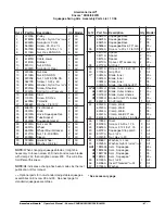
Page 76: ... S28 D28 S33 D33 S38 D38 WB American Lincoln Encore2 28 33 38 WB Solution Tank Assembly Drawing 11 06 1 2 3 4 5 6 7 8 9 10 11 12 13 14 15 18 17 16 19 20 45 22 23 24 21 25 26 27 21 24 21 28 29 30 31 32 31 30 33 34 35 36 37 38 39 40 41 42 43 12 44 46 47 ...

Page 77: ... HoseHangerBracket 1 20 59614A Battery Drain Valve 1 21 53571A HoseClamp 4 22 30453A Hose 1 23 822802 Elbow 1 24 30445A SolutionHose 2 25 50358A Connector 1 26 838517 FilterScreen 1 27 830214 HoseAdapter 1 28 50359A SolutionAdapter 1 29 53568A Hinge 1 30 980614 Washer 1 4External 6 31 85395A Screw 1 4 20 x 1 2 PN 6 32 30641A FrontCover 1 33 81105A Nut 3 8 16ESNA 2 34 930645 Washer 3 8Flat 2 35 962...

Page 78: ... Manual Encore2 S28 D28 S33 D33 S38 D38 WB American Lincoln Encore2 28 33 38 WB Recovery Tank Assembly Drawing 11 04 1 2 3 4 5 3 6 7 8 9 10 11 12 13 14 15 16 17 18 11 19 20 21 22 23 9 24 20 25 26 27 28 29 30 31 20 32 33 34 35 36 38 37 39 ...

Page 79: ...c Motor Spacer 3 16 45019A Vac Motor order 2 each 11 and 19 1 17 87026A Washer 1 4Flat 3 18 85728A Screw 1 4 20 x 4 Hex 3 19 43401A Housing Black 2 20 872010 Clamp 3 21 674110 Vac Exhaust Hose 1 22 962957 Screw 10 16 x 1 2 PN 2 23 52206A Chain 1 24 30620A SqueegeeAdapter 1 25 35192A SqueegeeHose 1 26 30227A DrainHousing 1 27 30226A DrainPlug 1 28 52560A O Ring 1 29 30225A DrainBody 1 30 832002 Dra...

Page 80: ...incoln Encore2 D28 D33 D38 WB Electrical Panel Assembly Drawing 11 04 1 2 3 4 5 3 6 8 7 9 5 5 10 22 11 7 12 13 5 6 14 15 16 18 17 19 20 21 20 21 5 25 24 23 26 27 28 29 30 31 5 40 18 38 39 38 5 35 31 32 33 37 5 34 ...

Page 81: ...54849 Insulator 2 16 170781 Screw Set 1 4 20 x 3 4 2 17 193951 Trim 8 1 18 83307A Stud 1 4 20 5 19 61589A ElectricalPanel 1 20 54764A Insert 1 4 20 4 21 54763A Insert 8 32 4 22 40742A MainWiringHarness Dlx 1 23 61680A Cable Spring 1 24 53424A Spring Cable 1 25 58409A Sleeve Spring 1 26 61681A Cable Upper 1 27 40892A Relay DPDT 1 28 85614A Screw 8 32 x 3 4 2 29 40743A Controller Trio 1 30 80105A Sc...

Page 82: ... D38 WB American Lincoln Encore2 S28 S33 S38 WB Electrical Panel Assembly Drawing 11 04 1 2 3 4 5 6 3 7 8 5 5 9 10 22 11 7 12 13 5 14 5 6 15 16 5 20 17 18 19 31 30 21 20 23 24 25 5 18 27 28 29 32 53 18 26 33 34 35 36 5 54 37 52 38 39 50 51 47 48 49 40 54 46 45 44 41 42 43 ...

Page 83: ... Insert 8 32 2 22 40736A MainWiringHarness Std 1 23 40125A Contactor Vacuum 1 24 41801A Contactor Brush 1 25 41802A Contactor Main 1 26 61682A Cable Upper 1 27 40735A Controller Solo 1 28 40759A TraverseHarness 1 29 80254A Screw 8 32 x 1 2 30 962666 Screw 10 24 x 3 4 1 31 912287 Rectifier 1 32 920296 Nut ESNA10 24 1 33 85700A Screw 1 4 20 x 1 1 34 87026A Washer 1 4Flat 2 35 608210 Spacer 1 36 6562...

Page 84: ... D33 S38 D38 WB American Lincoln Encore2 28 33 38 WB Control Panel Assembly Drawing 11 06 1 2 3 4 3 5 6 7 7 9 8 10 11 12 13 14 15 16 14 17 18A 18B 19 20 21 22 23 24 25 26 28 29 27 30 30 31 32 17 18A 18B 33 34 35 9 36 32 31 30 44 42 43 30 41 38 26 37 39 28 40 29 24 ...

Page 85: ... Position Rocker 1 24 962957 Screw 10 16 x 1 2 4 4 25 see table Label Control 1 26 34264A Gasket 1 1 27 see table Panel Control L 1 28 41431B Circuit Breaker 35A 2 2 29 41423B Circuit Breaker 5A 1 1 30 85391A Screw 1 4 20 x 5 8 3 3 31 980614 Washer 1 4 External 2 2 32 920208 Nut 1 4 20 2 2 33 962968 Screw 10 24 x 1 2 2 34 40749A Switch Momentary Rocker 1 35 47381B Switch Mantain Rocker 1 36 55502A...

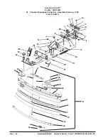
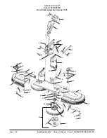
Page 86: ...e2 28 33 38 WB Squeegee Swing Arm Assembly Drawing 4 06 1 2 3 4 2 6 7 50 8 6 16 9 10 15 11 12 13 14 17 18 19 20 21 22 29 31 33 27 10 30 48 47 6 28 26 6 5 25 24 23 37 49 46 43 44 45 42 41 40 38 39 37 32 35 36 53 53 53 53 16 52 51 54 NOTE 51 and 52 are on top of the bracket for the S models 55 56 57 34 ...

Page 87: ...n made sinc the last publication of this manual Optional parts for non standard adjustable squeegee assemblies on Encore2 28 and 33 See next page for standardsqueegeeassemblies Ref Part No Description Qty Model 35 69673A SqueegeeBase 1 28 69674A SqueegeeBase 1 33 69675A SqueegeeBase 1 38 69636A Squeegee Base 29 acc 1 28 36 80316A Screw 20 x 1 Flat SS 2 All 37 38710A Spacer 2 28 38711A Spacer 2 33 ...

Page 88: ...incoln Operator s Manual Encore2 S28 D28 S33 D33 S38 D38 WB American Lincoln Encore2 28 33 WB Standard Squeegee Swing Arm Assembly Drawing 11 06 Form 10847A 35 36 37 38 41 39 40 42 27 43 44 53 45 46 47 48 49 50 51 52 54 ...

Page 89: ...all and secure blades with clamp 47 then retighten screw 52 This will allow for different thickness Ref Part No Description Qty 28 81217A Nut 20 1 29 920208 Nut Hex 20 1 30 980657 Washer Lock 1 31 87625A Washer Nylon1 x x1 32 4 32 81303A Nut 28 1 33 87026A Washer 4 34 87031A Washer 3 8 Flat 1 35 962720 Screw 20 x Hex 4 36 980657 Washer Lock 4 37 10803KL Squeegee Asm N A 38 60243A Bracket Sq Wheel ...

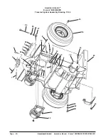
Page 90: ... Operator s Manual Encore2 S28 D28 S33 D33 S38 D38 WB American Lincoln Encore2 28 33 38 WB Traverse System Assembly Drawing 11 04 12 13 31 32 30 13 21 20 15 14 3 19 28 19 9 29 30 11 16 18 8 10 27 26 25 24 23 7 6 7 23 5 4 2 1 3 ...

Page 91: ...9116A Transaxle Imperial 1 All see page 46 45 for parts 15 85730A Screw Hex 4 All 16 59969A Wheel Assembly 2 All 59955A Wheel Foam Filled opt 2 All 18 81221A Lug Nut 50 20 UNF 6 All 19 980614 Washer Star Lock 25 3 All 20 61594A Main Frame 1 All 21 65963A TransaxleMount 2 All 23 87625A Washer Nylon 1 x IDx3 32 2 All 24 80011A Screw 3 8 16 x 3 2 All 25 81207A Nut 3 8 16 2 All 26 170883 Washer Lock 3...

Page 92: ...3 D33 S38 D38 WB American Lincoln Encore2 28 33 38 WB Brush Head Assembly Drawing 11 04 1 2 3 4 5 6 7 8 9 10 11 12 14 15 16 17 18 13 19 13 20 21 22 23 17 24 25 26 27 28 29 30 31 32 33 34 35 36 37 38 39 40 41 42 43 27 44 45 46 20 47 52 48 49 50 51 49 53 54 2 1 55 ...

Page 93: ... Screw 10 16x 88 6 All PadDriverOnly Ref Part No Description Qty Model 34 56941A Center Lock Asm 2 All PadDriverOnly 35 11427B Poly Brush Assembly 14 2 28 11424B Poly Brush Assembly 17 2 33 11434B Poly Brush Assembly 19 2 38 11426B Grit Brush Assembly 14 2 28 11425B Grit Brush Assembly 17 2 33 11433B Grit Brush Assembly 19 2 38 17521C PadDriverAssembly 14 2 28 17520C PadDriverAssembly 17 2 33 1752...

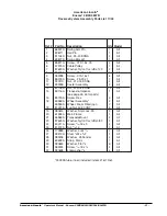
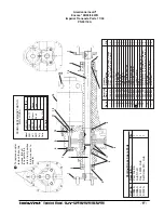
Page 94: ... Leads 6 50520A CommutatorBracket 1 7 56480A StrainRelief 2 8 962546 Brush Board Screw 2 9 50517A Brush Board Asm w springs brushes 1 10 448396 Brush Spring 4 11 40826A Brush Assembly 4 12 55657A Lead Assembly Positive 1 13 55656A LeadAssembly Negative 1 14 59805A Helical Washer 1 15 50515A Thru Bolt 2 16 80501A Shaft Key 1 17 54238A B E Bracket Assembly Gear Box 1 13 Seam Location 7 12 15 5 6 4 1...

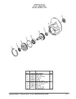
Page 95: ... 57846A Ring Snap 1 2 507641 Seal Oil Small 1 3 52050A CapEnd 1 4 56668A O Ring 1 5 51176A Bearing Large 1 6 58316A Shaft Gear Gearbox 1 7 902605 Bearing Small 1 8 54883A Housing 1 9 58144A Seal Oil Large 1 NI DarinaGrease 4oz 9 8 7 6 5 4 3 2 1 American Lincoln Encore2 28 33 38 WB Gear Box 54238A 11 04 ...

Page 96: ...ir Seal 1 19 53996A Fan Stationary 1 Ref Part No Description Qty 1 51913A Clip optional 2 2 54809A Housing 1 3 53905A Fan 1 4 85303A Screw 8 32 x 3 8 4 5 40830A CarbonBrushes 2 6 51914A Clamp 2 7 50618A Bracket 1 8 53100A Disc 1 9 902679 Bearing Ball 1 10 902648 Bearing ball radial 1 1 2 4 6 3 7 8 9 5 10 11 12 17 14 19 15 14 16 15 14 18 13 American Lincoln Encore2 28 33 38 WB Vac Motor Assembly 45...

Page 97: ...ge 1 10357A Studs Key Snap Rings Shims 2 2 36508A Rubber Mount 2 3 53374A Axle Oil Seal 2 4 53375A Axle Bearing 4 5 53376A Short Axle 1 6 53377A Output Gear 1 7 53378A Input Plug 1 8 53379A Outer Pinion Bearing 1 9 53380A Pinion 1 10 53381A Inner Pinion Bearing 1 11 52663A Steel Ring Coupler 1 12 69195A Rubber Coupler 1 13 45048A Motor 1 14 51720A Brushes w Springs Set of 4 1 15 30074A Motor Brush...

Page 98: ...incoln Operator s Manual Encore2 S28 D28 S33 D33 S38 D38 WB American Lincoln Encore2 S28 S33 S38 WB Control Panel Connection Diagram 11 04 American Lincoln Encore2 S28 S33 S38 WB Front of Machine Connection Diagram 11 04 ...

Page 99: ...n Operator s Manual Encore2 S28 D28 S33 D33 S38 D38 WB 99 American Lincoln Encore2 D28 D33 D38WB Control Panel Connection Diagram 11 04 American Lincoln Encore2 D28 D33 D38 WB Front of Machine Connection Diagram 11 04 ...

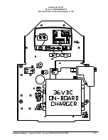
Page 100: ...Page 100 American Lincoln Operator s Manual Encore2 S28 D28 S33 D33 S38 D38 WB American Lincoln Encore2 S28 S33 S38 WB Electrical Plate Connection Diagram 11 04 ...

Page 101: ...American Lincoln Operator s Manual Encore2 S28 D28 S33 D33 S38 D38 WB 101 American Lincoln Encore2 D28 D33 D38 WB Electrical Plate Connection Diagram 11 04 ...

Page 102: ...Page 102 American Lincoln Operator s Manual Encore2 S28 D28 S33 D33 S38 D38 WB American Lincoln Encore2 S28 S33 S38 D28 D33 D38 WB Control Housing Connection Diagram 11 04 ...

Page 103: ...American Lincoln Operator s Manual Encore2 S28 D28 S33 D33 S38 D38 WB 103 American Lincoln Encore2 S28 S33 S38 WB Electrical Schematic 11 04 ...

Page 104: ...Page 104 American Lincoln Operator s Manual Encore2 S28 D28 S33 D33 S38 D38 WB American Lincoln Encore2 D28 D33 D38WB Electrical Schematic pages 58 59 11 04 ...

Page 105: ...American Lincoln Operator s Manual Encore2 S28 D28 S33 D33 S38 D38 WB 105 American Lincoln Encore2 D28 D33 D38 WB Electrical Schematic pages 58 59 11 04 ...

Page 106: ...NOTES ...

Page 107: ...derland B V Postbus 65 3370 AB Hardinxveld Giessendam The Netherlands 31 184 677 200 ALTO Sverige AB Molndal Sweden Aminogatan 18 Box 4029 S 431 04 Molndal 46 31 706 73 00 ALTO Norge A S Oslo Norway Bjornerudveien 24 N 1266 47 2275 1770 U S A Locations European Locations CORPO PRODUCTION FACILITIES Clarke Springdale Arkansas 2100 Highway 265 Springdale Arkansas 72764 479 750 1000 Customer Service ...

Page 108: ...rts or systems repaired or altered by a non authorized organization THEREARENOWARRANTIESTHATEXTENDBEYONDTHEDESCRIPTIONOFTHELIMITEDWARRANTIESSTATEDWITHIN NOOTHER WARRANTY EXPRESSED OR IMPLIED INCLUDING BUT NOT LIMITED TO ANY IMPLIED WARRANTY OF MERCHANTABILITY OR FITNESS FOR A PARTICULAR PURPOSE IS MADE EXCEPT AS EXPRESSLY STATED HEREIN ANY STATUTORY IMPLIED WARRANTIES INCLUDING ANY WARRANTY OF MER...

Reviews: