26 - FORM NO. 56041704
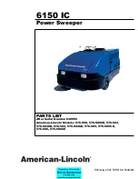
American-Lincoln
6150
TO EMPTY DEBRIS HOPPER
1. Adjust the throttle to a medium to high engine speed setting.
2. Engage parking brake.
3. Move the Hopper Dump door lever to the “CLOSE” Position until door is closed.
4. Move the hopper lift lever to the “RAISE” position until the hopper reaches the desired height.
5. Disengage Parking Brake.
6. Drive forward slowly with the hopper raised to clear refuse container before opening the hopper dump
door.
7. Engage Parking Brake.
8. Push the hopper dump door lever forward to the “OPEN” position. This will allow debris in the hopper to
fall out into the refuse container.
9. Move the hopper dump door lever to the “CLOSE” Position until door is closed.
10. Disengage Parking Brake. •
11. Drive in reverse slowly to clear the refuse container.
12. Engage Parking Brake.
13. Move the hopper lift lever forward to the “LOWER” position and hold until hopper is seated in place.
14. Move the hopper dump door lever to the “OPEN” position until the dump door opens.
WARNING
Do Not Turn off the engine with the hopper in the lifted position.
NOTE
After Stopping The Engine, Perform These Post Operation Checks.
POST OPERATION CHECK LIST
1. Clean debris hopper.
2. Check sweeping brooms for wear or damage.
3. Check all fl aps for wear, damage and adjustment.
4. Fill the fuel tank.
5. Check all systems for leaks.
6. Close the LP storage tank valve. (LP Powered machines only)
WARNING
The Gasoline Tank Fill Cap Is Located Behind The Drivers Seat, Do Not Mistake The Hydraulic Reservoir For The
Gasoline Tank.
BATTERY CHARGING INSTRUCTIONS (Battery powered Machines Only)
Charge the batteries at the end of each day or when the battery condition meter indicates low battery
voltage. The batteries need to be charged when the needle stays in the “red” zone while the machine is being
operated. When charging the batteries, only use the quick disconnect provided in ensure correct polarity.
Check the liquid level in the batteries at least once a week and add water when low. Use only distilled
water. Fill the batteries after charging the batteries to prevent electrolyte from spilling over on the tops of the
batteries during the charging process.
WARNING
The use of an extension cord with the charger should be avoided. Risk of fi re and electrical shock
is possible if the wrong type or size extension cord is used. If an extension cord must be used, only
use a three conductor number 12 AWG cord with ground, properly wired, in good electrical condition
and keep it as short as possible. Locate all cords so that they cannot be stepped on, tripped over, or
otherwise subjected to damage or stress.
OPERATING INSTRUCTIONS
Summary of Contents for 6150
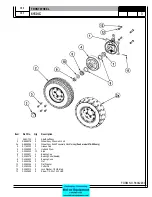
Page 39: ...FORM NO 56042480 6150 IC 4 06 5 REAR WHEEL 07 10 ...
Page 41: ...FORM NO 56042480 6150 IC 6 06 5 VAC FAN 07 10 ...
Page 45: ...FORM NO 56042480 6150 IC 10 06 5 FLAP ASSEMBLY WHEEL WELL 07 3 C 1227 ...
Page 51: ...FORM NO 56042480 6150 IC 16 06 5 C1250 H46 H43 H39 H47 H53 SIDE BROOM ASSEMBLY 07 3 ...
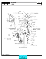
Page 53: ...FORM NO 56042480 6150 IC 18 06 5 SIDE BROOM LIFT SYSTEM 07 10 ...
Page 57: ...FORM NO 56042480 6150 IC 22 06 5 BROOM CHAMBER FLAPS SEALS 07 10 ...
Page 59: ...FORM NO 56042480 6150 IC 24 06 5 BRAKE PEDAL 80805 1 6 05 07 3 ...
Page 63: ...FORM NO 56042480 6150 IC 28 06 5 SEAT FLOOR ASSEMBLY 07 10 ...
Page 71: ...FORM NO 56042480 6150 IC 36 06 5 CONTROL RELIEF VALVE 3 CYL KUBOTA GAS DIESEL 07 3 ...
Page 73: ...FORM NO 56042480 6150 IC 38 06 5 FWD REV CONTROL 2 CYL KAWASAKI GAS 07 10 ...
Page 75: ...FORM NO 56042480 6150 IC 40 06 5 FW REV CONTROL 3 CYL KUBOTA GAS DIESEL 07 3 ...
Page 81: ...FORM NO 56042480 6150 IC 46 06 5 FUEL TANK GAS 07 10 ...
Page 83: ...FORM NO 56042480 6150 IC 48 06 5 FUEL TANK DIESEL 07 10 ...
Page 87: ...FORM NO 56042480 6150 IC 52 06 5 80806 2 2 05 HOPPER COVERS GASKET ASSEMBLY ...
Page 91: ...FORM NO 56042480 6150 IC 56 06 5 H26 H80 H86 H26 H98 H22 C 1207 9701 DUMP DOOR ...
Page 97: ...FORM NO 56042480 6150 IC 62 06 5 HYDRAULIC PUMP 3 CYL KUBOTA GAS DIESEL 07 3 80851 SHT01 ...
Page 99: ...FORM NO 56042480 6150 IC 64 06 5 ENGINE COVER 30 25 32 31 80813 0 3 07 ...
Page 101: ...FORM NO 56042480 6150 IC 66 06 5 80841 8 05 ACCESS COVER ASSEMBLY ...
Page 105: ...FORM NO 56042480 6150 IC 70 06 5 ENGINE 3 CYL KUBOTA GAS 07 10 ...
Page 107: ...FORM NO 56042480 6150 IC 72 06 5 ENGINE 3 CYL KUBOTA DIESEL 07 10 ...
Page 109: ...FORM NO 56042480 6150 IC 74 06 5 ENGINE 3 CYL DUAL FUEL LP 07 10 ...
Page 113: ...FORM NO 56042480 6150 IC 78 06 5 80839revF 8 05 HYDRAULIC HOSE DIAGRAM 2 CYL ...
Page 125: ...FORM NO 56042480 6150 IC 90 06 5 DECALS 08 7 ...
Page 127: ...FORM NO 56042480 6150 IC 92 06 5 DECALS continued 07 10 ...
Page 129: ...FORM NO 56042480 6150 IC 94 06 5 C1335 7 04 2 CYLINDER LP CE MODELS ONLY ...
Page 136: ...101 FORM NO 56042480 6150 IC 06 5 HYDRAULIC SCHEMATIC 2 CYL GAS LP DIESEL 08 7 ...
Page 138: ...103 FORM NO 56042480 6150 IC 06 5 HYDRAULIC SCHEMATIC 3 CYL KUBOTA GAS DIESEL ...


